In this detailed tutorial, we’ll explore the process of making a water level controller without the need for a microcontroller. This project serves as an excellent opportunity to deepen your understanding of electronic components and their behaviours in circuits, paving the way for designing complex circuits without relying on microcontrollers like Arduino, PIC, or ESP32.
To successfully design such a circuit, it’s crucial to master the behaviours of various electronic components. These components include resistors, capacitors, transistors, relays, thyristors, sensors, transformer, bridge rectifiers, voltage regulators, etc. each playing a vital role in the circuit’s functionality.
Understanding how these components interact is key to designing an effective water level controller. For instance, sensors detect the water level and send signals to the circuit. Transistors act as switches, controlling current flow based on sensor input. Resistors and capacitors manage voltage and current flow for stability. Relays switch high-power loads like pumps, thyristors handle power control, transformer and bridge rectifiers convert AC to DC, and voltage regulators maintain a stable output DC voltage.
By delving into the intricacies of these components and their roles in circuit design, you’ll not only create a functional water level controller but also gain valuable insights for future projects. This journey of discovery will empower you to design innovative electronic circuits without relying on microcontrollers.
List of Materials for the Circuit Design
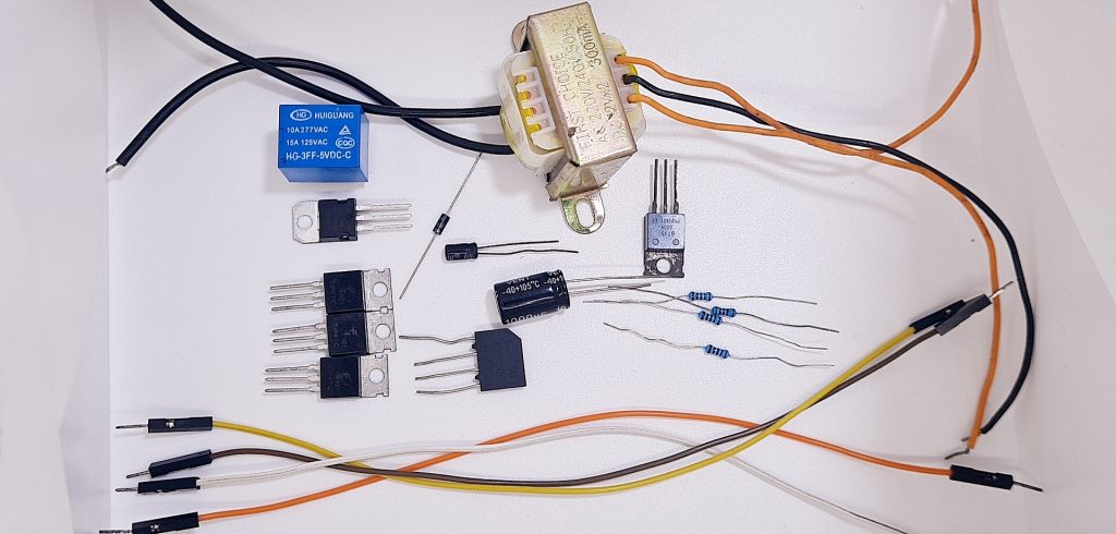
| S/N | Component | Description | Quantity |
| 1 | Resistor | 100R | 4 |
| 2 | Transistor | TIP41 | 3 |
| 3 | Thyristor | BT151 | 1 |
| 4 | Transformer | 220V to 12V | 1 |
| 5 | Bridge rectifier | KBP206 | 1 |
| 6 | Capacitor | 1000uF, 1uF | 2 |
| 7 | Voltage regulator | 7805 | 1 |
| 8 | Diode | 1N4001 | 1 |
| 9 | Relay | 5V SPDT | 1 |
| 10 | Jumper wires | Male to male | Bunch |
Images of the electronic components used in the project
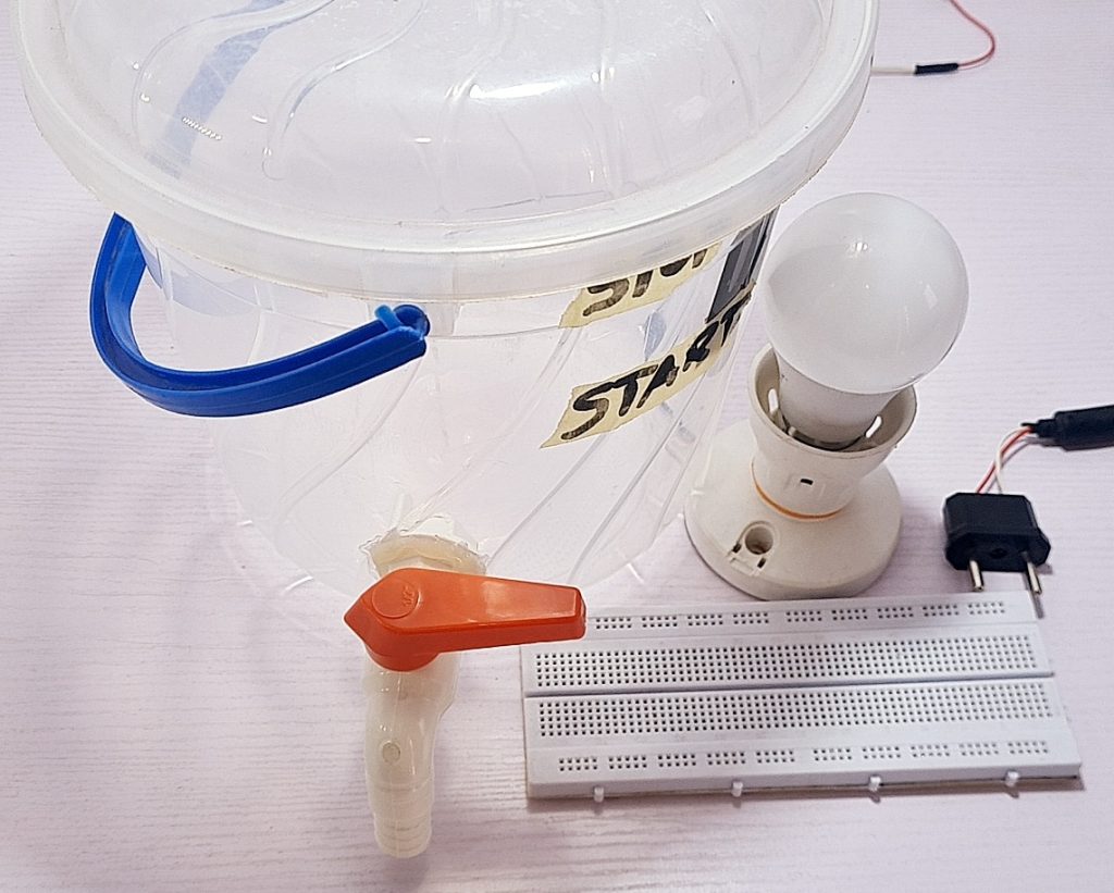
Tools and Other Materials Used for the Project
- Breadboard
- Lamp Holder
- 220V AC Bulb (Improvised Pump)
- Bucket with tap (Improvised Tank)
- 220V AC Plug
Parts of the Circuit
The project’s circuit consists of two main parts: the power supply and the water level controller.
Power Supply
The power supply is responsible for converting AC to DC to provide the necessary electrical energy for the circuit to operate. This is achieved using components such as a transformer, bridge rectifier, capacitors, and voltage regulators. These components work together to ensure a stable DC voltage output, essential for the circuit’s operation.
Below is the circuit diagram of the power part of the circuit

Water Level Controller
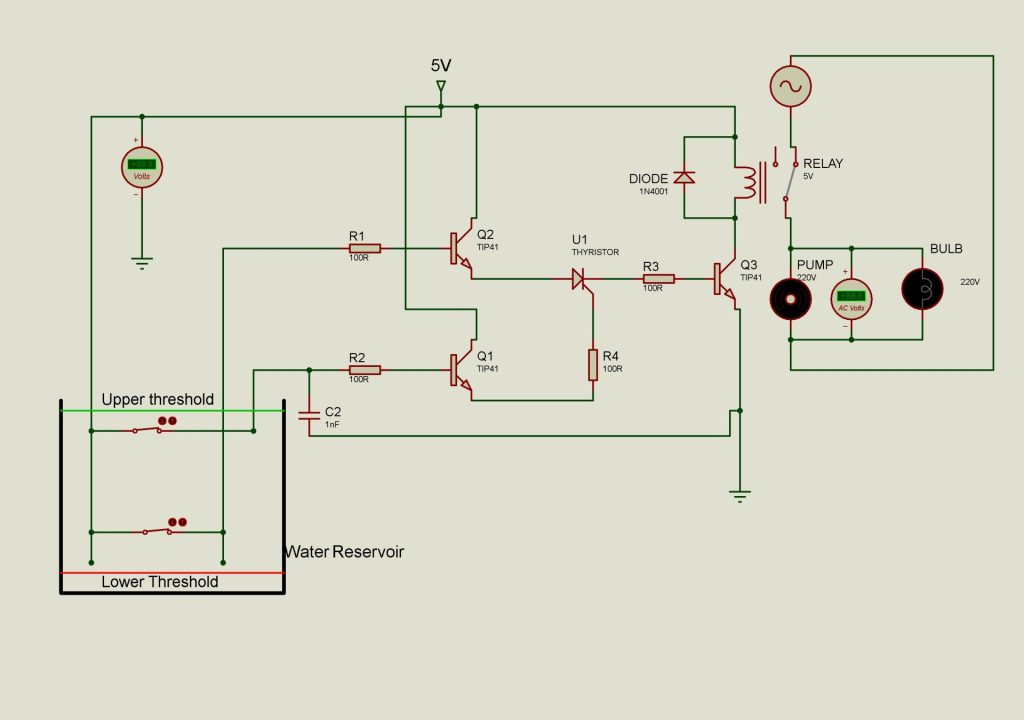
On the other hand, the water level controller part of the circuit includes components such as wires serving as sensors, transistors acting as switches, thyristors for current flow control, relays as contactless switches, and resistors and capacitors for managing current flow. These components work in harmony when connected correctly to create an automatic water level controller device.
When the water level reaches a certain point, the sensors detect the change and send a signal to the transistors, which act as switches, allowing current to flow through the thyristor. The thyristor then controls the current flow, activating the relay to switch the water pump on or off, maintaining the water level within the desired range.
By understanding and appropriately connecting these components, you can create an efficient and reliable automatic water level controller device.
Below is the circuit diagram of the water level controller part of the circuit
Circuit Diagram and Explanation for the project
Below is the complete circuit diagram and explanation of the entire project
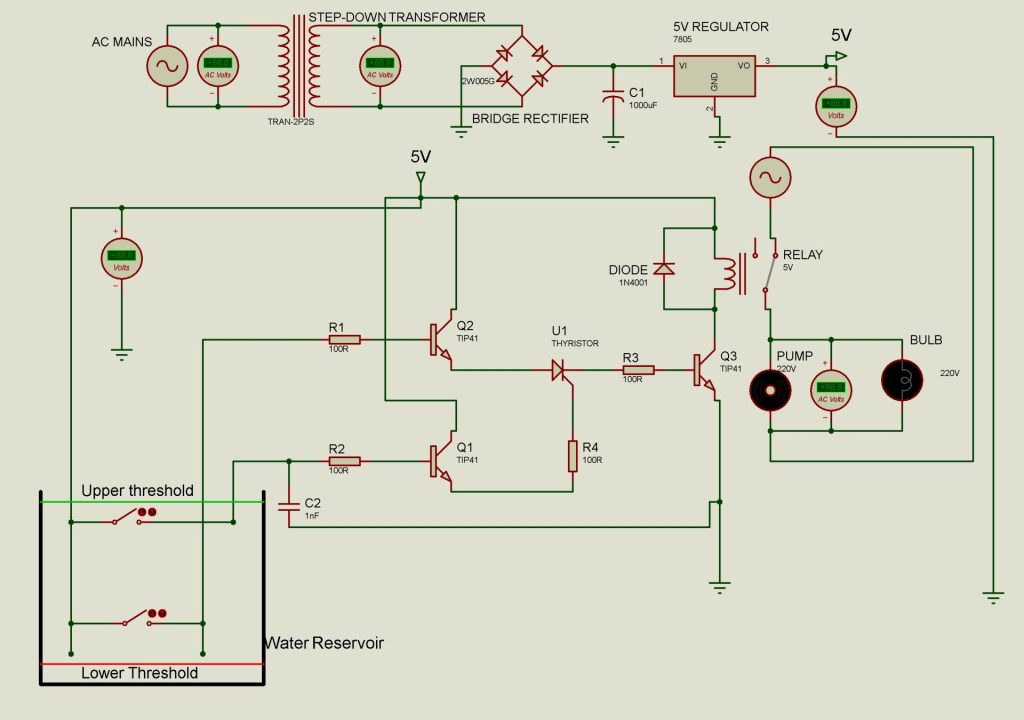
Circuit Explanation
Power Supply Design Breakdown:
The circuit starts by converting household current to a usable voltage level, 5V to be precise.. Here’s how it’s done:
- Step-Down Transformer: The incoming 220V AC (Alternating Current) first passes through a transformer. This transformer acts like a voltage converter, stepping down the high voltage to a lower level, typically 12V AC.
- Bridge Rectifier: Next, the 12V AC gets converted to DC (Direct Current) by a bridge rectifier. This component allows current to flow in only one direction, eliminating the negative voltage swings of AC.
- Filtering Capacitor: The raw DC output from the rectifier can still have some fluctuations. A filtering capacitor smooths out these ripples, providing a cleaner DC signal.
- Voltage Regulator: Finally, the filtered DC reaches the voltage regulator. This component acts like a control valve, ensuring a steady and stable output voltage, usually around 5V DC in this case. This stable voltage is what powers the rest of the circuit.
Water level Controller Circuit Breakdown
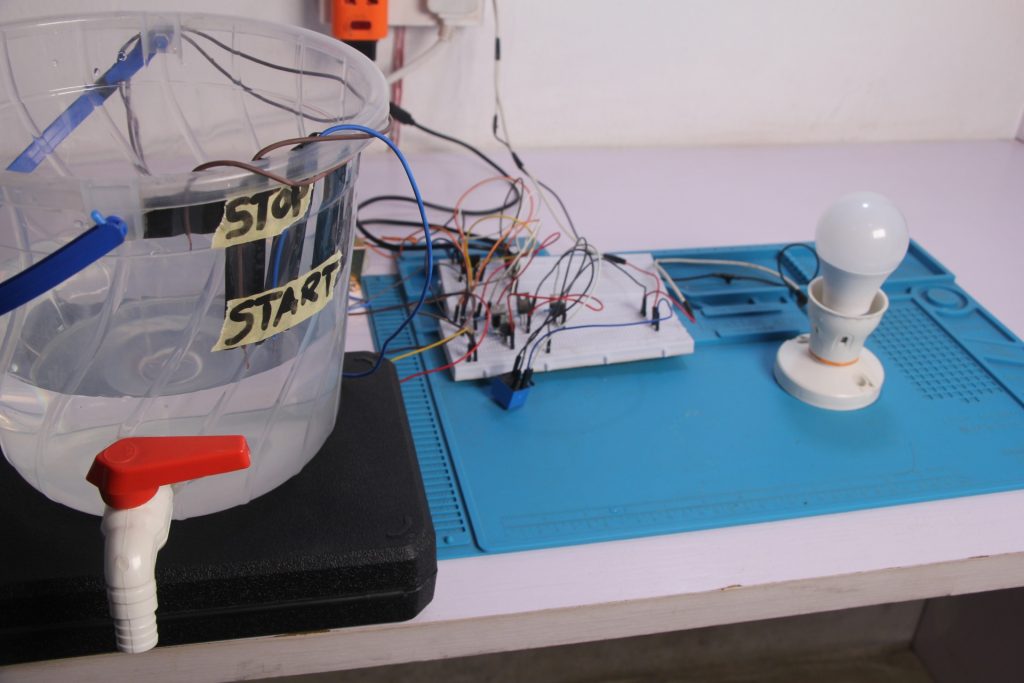
The circuit utilizes a 5V DC power supply to operate the water level controller. Initially, with no water in the tank, the AC current passes through the normally closed terminal of the relay, powering the pump (represented by an AC bulb and a motor). This indicates that water is being pumped into the tank.
When the water touches the two wires at the lower threshold, current from the 5V DC flows through the water and into the base of transistor Q2 via resistor R1. This causes collector current to flow through transistor Q2 and into the anode of the thyristor. However, since the gate of the thyristor is not yet fired, it does not conduct electricity, and current does not flow through it.
As the water level reaches the upper threshold of the tank and touches the two wires, current flows from the 5V DC source into the base of transistor Q1 through resistor R2. This causes collector current to flow through transistor Q1 and into the gate of the thyristor via resistor R4, firing the thyristor. Once the thyristor is fired, it conducts, allowing current to flow from its anode to cathode. This current biases transistor Q3, causing collector current to flow through the relay, energizing it. The relay then switches its common (com) terminal from the normally open (NO) to the normally closed (NC) terminal, cutting off the current supply to the pump and stopping water from pumping into the tank.
As the water level drops below the upper threshold, the current supply to the thyristor’s gate is cut off. However, since a thyristor continues to conduct even after the firing current is removed, the relay remains energized, and the pump remains off.
When the water level falls below the lower threshold, the current to the thyristor’s anode is cut off. This causes the current to the transistor that drives the relay to be cut off as well. With transistor Q3 no longer conducting electricity, the relay de-energizes, returning to its default state. This action allows AC current to flow into the pump, turning it on and restarting the water flow into the tank.
This cycle continues as long as there is a power supply, ensuring a continuous water level in the tank.
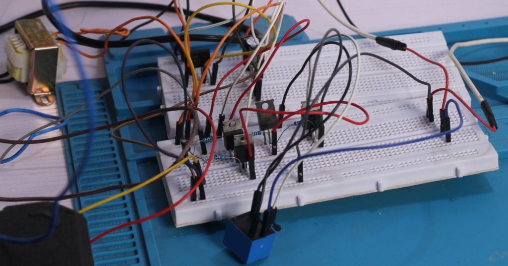
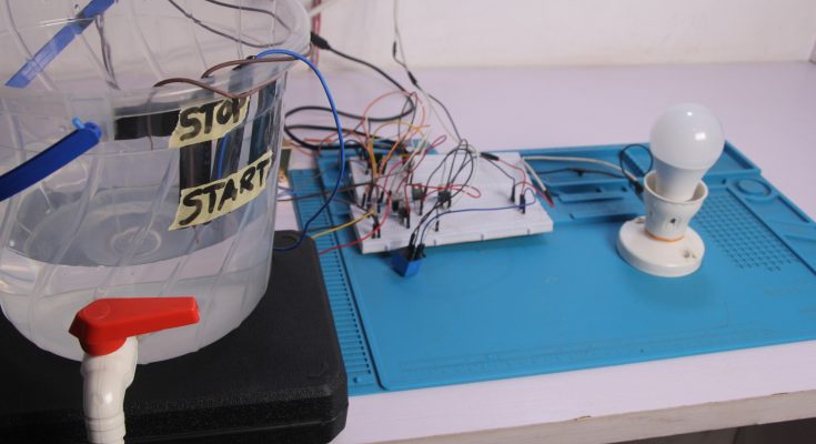
Below is the physical circuit on a breadboard
If you’re interested in undertaking this project and need the components used in it, feel free to reach out to us for procurement. Additionally, if you require technical assistance or would like us to help you with the project, don’t hesitate to contact us.
We would like to get your feedback on this project in the comment section.
This is Superb! 🤍
Nicely done and very detailed.
Good job
I would like to undertake the automatic water level controller project, i would like to procure the components please