TUTORIALS

How to program an bostacle avoidance robot with a Smartphone

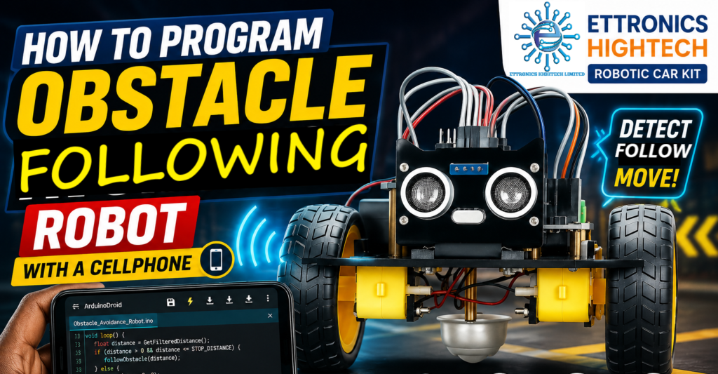
How to Program the Ettronics Hightech Obstacle Following Robot

The Ettronics Hightech Robotic Car is an Arduino-based educational robot designed to introduce learners to Arduino programming, sensors, motor control, and autonomous robotics. The same robotic car can be programmed to perform different tasks, including obstacle avoidance, obstacle following, and remote-controlled operation. In our previous tutorial, we programmed the Ettronics Hightech Robotic Car to operate as an obstacle avoidance robot. In that mode, the robot detects an obstacle in front of it and then takes action to avoid it. In this tutorial, we are going to program the same robotic car to operate as an obstacle following robot. This time, instead of avoiding the object in front of it, the robot will use the HC-SR04 ultrasonic sensor to monitor the distance between itself and the object. Depending on that distance, it will either move forward, stop, or reverse. The robot is programmed using an Arduino Nano, an HC-SR04 ultrasonic sensor, and an L9110 motor driver. As with the previous tutorial, the Arduino Nano can be programmed using an Android smartphone and the ArduinoDroid app, so a computer is not required. Watch the Robotic Car Assembly and Wiring Tutorial First Before programming the robotic car, the components need to be properly assembled and connected. If you have not yet assembled your Ettronics Hightech Robotic Car, watch our robotic car assembly and wiring tutorial first. In that video, we demonstrate how to assemble the mechanical parts of the car and connect the Arduino Nano, L9110 motor driver, ultrasonic sensor, motors, and other components. Watch how to Program the Ettronics Hightech Obstacle Following Robot Ettronics Hightech Robotic Car Kit | Full Assembly & Connection Guide After completing the assembly and connections, you can proceed with this programming tutorial. If you are yet to get the Ettronics Hightech Robotic Car, you can click here to purchase it. BUY THE ETTRONICS HIGHTECH ROBOTIC CAR KIT Watch How to Program The Ettronics Hightech Obstacle Following Robot What You Need For this tutorial, you need: Your Android phone should be running Android 8.0 or later. How the Obstacle Following Robot Works The basic idea behind this project is simple. The HC-SR04 ultrasonic sensor measures the distance between the robotic car and the object in front of it. The Arduino Nano then uses that distance to decide what the car should do. There are several distance points programmed into the robot. The main stop limit is: This means that when the object is more than 55 cm away, the robot stops. When an object is detected at 55 cm or less, the robot starts applying the obstacle-following instructions. The programmed following range is: This means: So the robot does not simply chase an object from any distance. If the object is farther than 55 cm, the robot stops and waits for the object to come within its programmed detection range. The behavior can be summarized as: Object farther than 55 cm → STOP Object between 45 and 55 cm → MOVE FORWARD Object between 25 and 45 cm → MOVE FORWARD Object between 15 and 25 cm → STOP briefly, then MOVE FORWARD Object closer than 15 cm → REVERSE, then MOVE FORWARD Arduino Nano and the CH340 USB Interface The controller used in this robotic car is the Arduino Nano based on the ATmega328P. This particular Nano uses the CH340 USB-to-serial interface for communication between the Arduino and the USB port. This is important when programming the board from an Android phone because the phone needs to communicate with the Nano through its USB interface. Connecting the Android Phone to the Arduino Nano The first thing you need is a USB OTG adapter. Connect the components as follows: Android phone → OTG adapter → USB cable → Arduino Nano Once connected, Android may display a message asking whether you want to allow the ArduinoDroid application to access the connected USB device. Allow the connection. If ArduinoDroid does not detect the board immediately, check that: Install ArduinoDroid Install the ArduinoDroid application on your Android phone. The phone used for this tutorial should have Android 8.0 or newer. ArduinoDroid provides an Arduino development environment directly on an Android device, allowing you to write, compile, and upload Arduino programs without using a computer. Once the application is installed, connect the Arduino Nano to your phone through the USB OTG adapter. Arduino Nano Connections The Arduino Nano is connected to the L9110 motor driver through the Arduino-compatible extension board used in the Ettronics Hightech Robotic Car. The motor control connections are: Arduino Nano L9110 Motor Driver D5 A-1A D6 A-1B D9 B-1A D10 B-2B The HC-SR04 ultrasonic sensor is connected as follows: HC-SR04 Arduino Nano VCC 5V GND GND TRIG A4 ECHO A5 The Arduino uses these pins to control the two motors and communicate with the ultrasonic sensor. Setting Up ArduinoDroid After connecting the Nano to your Android phone, open ArduinoDroid. Create a new Arduino sketch and select the appropriate Arduino board. To do so: The Obstacle Following Program The following is the program used for the Ettronics Hightech Obstacle Following Robotic Car. The motor and ultrasonic sensor connections remain the same as in the previous project. The major change is the program logic. Instead of checking for an obstacle and then turning away from it, the Arduino continuously checks the measured distance and decides whether the robot should move forward, stop, or reverse. The robot uses a maximum forward speed of 255. Understanding the Important Parts of the Program You don’t need to understand every line before uploading the program. However, understanding the major sections will help you modify the robot later and develop your own robotic projects. 1. Defining the Motor Directions At the beginning of the program, we define four movement directions and a stop command: These names make the rest of the program easier to understand. Instead of writing complicated motor commands every time we want the robot to move, we can simply write: or: 2. Ultrasonic Sensor Connections The HC-SR04 uses two signal pins.

How to Program the Ettronics Hightech Obstacle Following Robot Read More »

How to program Arduino with a Cellphone

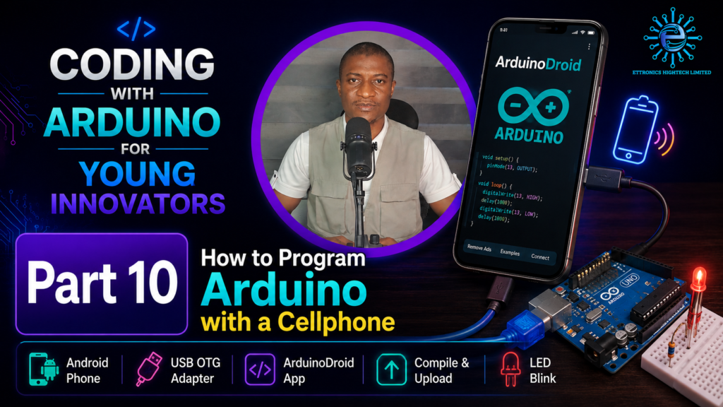
How to Program Arduino with a Cellphone

Learning Arduino programming doesn’t require an expensive laptop or desktop computer. If you have an Android smartphone, you already have a complete portable setup for building, compiling, and uploading code to a microcontroller. As part of the Coding with Arduino for Young Innovators series (Part 10) using the Ettronics Hightech Arduino kit, this guide walks you through programming an Arduino Uno directly from an Android phone. You will build a basic LED circuit, upload your first program, and modify the code to control how fast the LED blinks. Prerequisites & Components All circuit components used in this tutorial are included in the Ettronics Hightech Arduino Kit. Hardware Requirements: Software Requirements: Step-by-Step Guide 2. Build the LED Circuit: Connect your components as shown in the circuit diagram above 3. Connect Arduino Board to Your Cellphone: Plug the OTG adapter directly into your Android smartphone’s charging port, Connect the standard USB end into the USB OTG adapter, then plug the USB cable into the Arduino Uno. Once connected, your phone supplies power directly to the Arduino board. 4. Set up the Arduino Board in the Arduinodroid App: 5. Load the Blink Example: Open the app menu and navigate to: Sketch > Examples > Basics > Blink. The example loads the standard blinking code into the editor: The code above above is what you will see on the Arduinodroid blink example code. It is the same thing as the code below. 5.Compile and Upload the Code: Modifying Code & Changing LED Speed Built-in example sketches are read-only. To experiment with the code: To alter the performance of the circuit, update the delay parameter: Code Modification Delay Duration LED Behavior delay(1000); 1.0 Second Standard default blink rate delay(500); 0.5 Seconds Blinks twice as fast delay(100); 0.1 Seconds Rapid blinking pulse Compile and upload the modified sketch to update the microcontroller instantly. Key Takeaways Frequently Asked Questions Can I program Arduino using an iPhone? No. iOS limits raw USB OTG hardware communications required by microcontrollers. This setup relies on Android’s USB host driver capabilities. Why does the phone ask for USB permission when uploading? Android protects hardware ports by requiring explicit permission before allowing an application to send hex files over serial data pins to connected microcontrollers. Do I need an external battery for the Arduino while connected to the phone? No. The phone’s USB OTG port provides 5V power, which is sufficient to power the Arduino Uno and small components like single LEDs or sensors. Tutorial video You can watch the tutorial video for the project below

How to Program Arduino with a Cellphone Read More »

How to program an bostacle avoidance robot with a phone

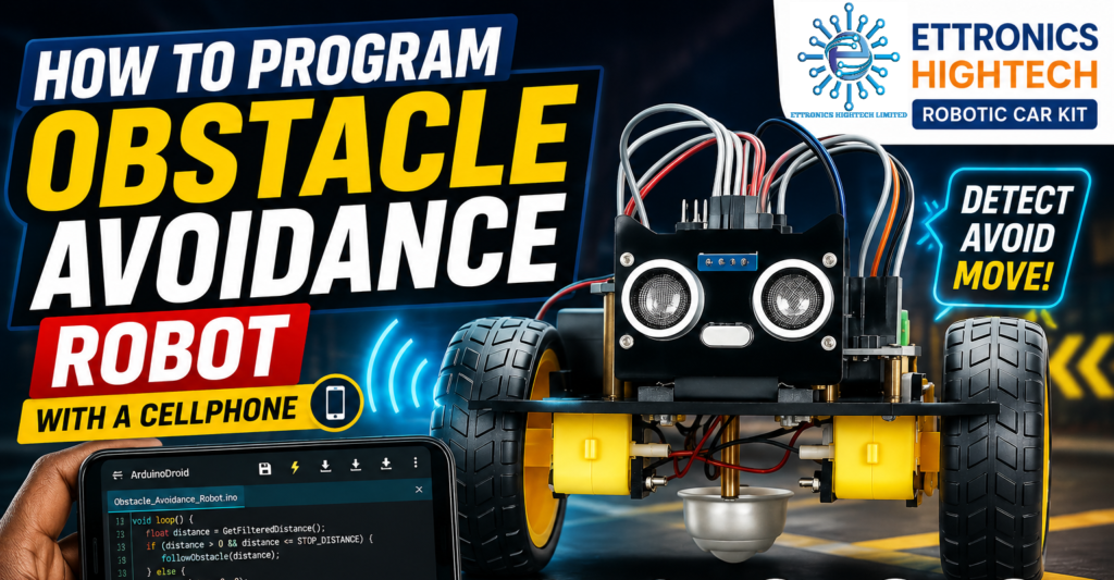
How to Program the Ettronics Hightech Obstacle Avoidance Robotic Car

The Ettronics Hightech Robotic Car is an Arduino-based educational robot designed to introduce learners to Arduino programming, sensors, motor control, and autonomous robotics. It can be programmed to operate as an obstacle avoidance robot, obsatcle following robot and remote controlled robot. In this tutorial, we will program the robotic car to oprate as an obsatcle avoidance robot using an Android smartphone and the ArduinoDroid app. You do not need a computer to upload the program to the Arduino Nano. The robotic car uses an Arduino Nano ATmega328P with the CH340 USB interface, an L9110 motor driver, and an HC-SR04 ultrasonic sensor. Once programmed, the robot can detect obstacles in front of it, stop, reverse, choose a new direction, and continue navigating autonomously. Watch the Robotic Car Assembly and Wiring Tutorial First Before programming the robotic car, the components need to be properly assembled and connected. If you have not yet assembled your Ettronics Hightech Robotic Car, watch our robotic car assembly and wiring tutorial first. In that video, we demonstrate how to assemble the mechanical parts of the car and connect the Arduino Nano, L9110 motor driver, ultrasonic sensor, motors, and other components. After completing the assembly and connections, you can proceed with this programming tutorial. and if you are yeet to get the Ettronics Hightech Robotic car, you can click here to purchase it now. BUY THE ETTRONICS HIGHTECH ROBOTIC CAR KIT Watch How to Program the Ettronics Hightech Obstacle Avoidance Robot What You Need For this tutorial, you need: Your Android phone should be running Android 8.0 or later. How the Robotic Car Works The basic principle behind the robot is quite simple. The HC-SR04 ultrasonic sensor continuously measures the distance between the car and objects in front of it. When the path is clear, the Arduino commands the motors to move the car forward. When an obstacle is detected within the programmed detection distance, the Arduino: The program also uses filtered ultrasonic readings. This is particularly useful when the car is operated on rough surfaces such as interlocking pavement, where vibration can sometimes cause unstable ultrasonic readings. Arduino Nano and the CH340 USB Interface The controller used in this robotic car is the Arduino Nano based on the ATmega328P. This particular Nano uses the CH340 USB-to-serial interface for communication between the Arduino and the USB port. This is important when programming the board from an Android phone because the phone needs to communicate with the Nano through its USB interface. Connecting the Android Phone to the Arduino Nano The first thing you need is a USB OTG adapter. BUY THE ETTRONICS HIGHTECH ARDUINO KIT Connect the components as follows: Android phone → OTG adapter → USB cable → Arduino Nano Once connected, Android may display a message asking whether you want to allow the ArduinoDroid application to access the connected USB device. Allow the connection. If the ArduinoDroid application does not detect the board immediately, check that: Install ArduinoDroid Install the ArduinoDroid application on your Android phone. The phone used for this tutorial should have Android 8.0 or newer. ArduinoDroid provides an Arduino development environment directly on an Android device, allowing you to write, compile, and upload Arduino programs without using a computer. Once the application is installed, connect the Arduino Nano to your phone through the USB OTG adapter. Arduino Nano Connections The Arduino Nano is connected to the L9110 motor driver through the Arduino-compatible extension board used in the Ettronics Hightech Robotic Car. The motor control connections are: Arduino Nano L9110 Motor Driver D5 A-1A D6 A-1B D9 B-1A D10 B-2B The HC-SR04 ultrasonic sensor is connected as follows: HC-SR04 Arduino Nano VCC 5V GND GND TRIG A4 ECHO A5 The Arduino uses these pins to control the two motors and communicate with the ultrasonic sensor. Setting Up ArduinoDroid After connecting the Nano to your Android phone, open ArduinoDroid. Create a new Arduino sketch and select the appropriate Arduino board. To do so, The Obstacle Avoidance Program The following is the program used for the Ettronics Hightech Obstacle Avoidance Robotic Car. The program has been designed to provide stable operation even when the robot is driven on relatively rough surfaces. Compiling and uploading the code Once the code is uploaded, the car wheels will start moving automatically. At this point, unplug the robotic car from the phone, put the car on the floor and turn on the battery switch, the car will start moving on its own while avoiding obstacles. Please note that the Android App used (ArduinoDroid) is a Freemium App, hence, if you want to remove ads from the app when using it, you can pay to purchase it, however, you can use the free version but with ads and limited use each time the app is opened. Understanding the Important Parts of the Program You don’t need to understand every line before uploading the program. However, understanding the major sections will help you modify the robot later and develop your own robotic projects. 1. Defining the Motor Directions At the beginning of the program, we define four movement directions and a stop command: These names make the rest of the program easier to understand. Instead of writing complicated motor commands every time we want the robot to move, we can simply write: or: 2. Ultrasonic Sensor Connections The HC-SR04 uses two signal pins. The TRIG pin sends the ultrasonic pulse, while the ECHO pin receives the reflected signal. In our robot: Therefore: The sensor is powered from the Arduino’s 5 V and GND connections. 3. Controlling the Motors The L9110 motor driver allows the Arduino to control the direction and speed of the two motors. The connections are: Arduino Nano L9110 D5 A-1A D6 A-1B D9 B-1A D10 B-2B The Arduino uses PWM signals on these pins to control the motor speed. For example: commands both motors to move the robot forward at maximum speed. 4. Starting Slowly and Accelerating We don’t immediately start the robot at maximum speed. The program

How to Program the Ettronics Hightech Obstacle Avoidance Robotic Car Read More »

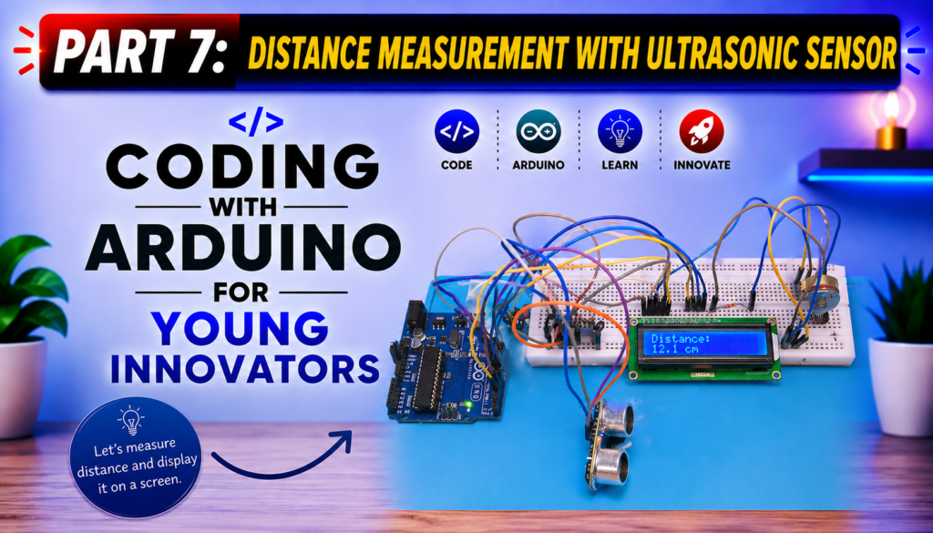
Distance Measurement with Arduino & Ultrasonic Sensor

Measuring distance without touching an object is one of the most useful applications of electronics and embedded systems. From automatic doors and robot navigation to parking assistance systems and industrial automation, contactless distance measurement is widely used in modern technology. In this tutorial, you will learn how to build a digital distance meter using an Arduino Uno, an HC-SR04 Ultrasonic Sensor, and a 16×2 LCD Display. By the end of this project, your Arduino will continuously measure the distance to an object and display the measurement in real time on an LCD screen. This project is suitable for beginners who already have basic knowledge of Arduino programming and breadboard connections. Project Demonstration When the project is completed: Learning Objectives After completing this project, you will understand how to: Components Required Component Quantity Arduino Uno R3 1 HC-SR04 Ultrasonic Sensor 1 16×2 LCD Display 1 5k Potentiometer 1 220Ω Resistor 1 Breadboard 1 Jumper Wires Several USB Cable 1 How the Ultrasonic Sensor Works The HC-SR04 ultrasonic sensor measures distance using high-frequency sound waves of about 40,000Hz or 40kHz It has four pins: The sensor also contains: The Arduino sends a short pulse to the Trig pin. The sensor then emits an ultrasonic wave (approximately 40 kHz). When this sound wave hits an object, it reflects back toward the sensor. The sensor detects the returning echo and sends the information back to the Arduino. The Arduino measures how long the sound took to travel to the object and back. Using the speed of sound (approximately 340 m/s), the Arduino calculates the distance. The calculated value is then displayed on the LCD. Insert illustration showing ultrasonic wave transmission and reflection Understanding the LCD Display The 16×2 LCD contains: It allows us to display text, numbers, and sensor readings. A 5k potentiometer is connected to adjust the LCD contrast for clear visibility. Circuit Diagram The circuit consists of three major sections: The ultrasonic sensor connects to Arduino digital pins. The LCD communicates with the Arduino using 4-bit mode. The potentiometer controls LCD contrast. The resistor limits current through the LCD backlight. Circuit Connections Ultrasonic Sensor HC-SR04 Arduino VCC 5V GND GND Trig Pin 9 Echo Pin 10 LCD Connections LCD Pin Arduino RS Pin 12 E Pin 11 D4 Pin 4 D5 Pin 5 D6 Pin 6 D7 Pin 7 VSS GND VDD 5V VO Potentiometer Middle Pin A 5V through 220Ω resistor K GND Potentiometer Connections Potentiometer Connection Left Pin 5V Middle Pin LCD VO Right Pin GND Arduino Program The Arduino program performs the following tasks: Understanding the Program Including the LCD Library The program begins by including the LiquidCrystal library, which allows the Arduino to communicate with the LCD display. Initializing the LCD The LCD object is created using the Arduino pins connected to the LCD. Setting Sensor Pins The Trig pin is configured as an output. The Echo pin is configured as an input. Measuring Distance The Arduino sends a short pulse to the Trig pin. The sensor transmits ultrasonic waves. The Echo pin measures how long it takes for the sound to return. The Arduino converts this travel time into distance using the speed of sound. Displaying the Result The calculated distance is displayed on the LCD. If the object is outside the measurable range, the LCD displays: Testing the Project After uploading the code: The displayed distance should update continuously. Applications This project forms the basis of many real-world systems, including: Troubleshooting LCD Shows Nothing Incorrect Distance LCD Displays Random Characters “Out of Range” Always Appears Conclusion In this project, you successfully built a contactless digital distance meter using an Arduino Uno, an HC-SR04 Ultrasonic Sensor, and a 16×2 LCD Display. Along the way, you learned how ultrasonic sensors measure distance, how to interface an LCD with Arduino, and how to write a program that displays real-time measurements. These are essential skills that form the foundation for more advanced Arduino and robotics projects. In the next lesson, we’ll continue building practical Arduino projects that introduce new sensors, programming concepts, and real-world applications. Checkout other Arduino Programming Tutorials Arduino LED Blink Tutorial for Beginners | Coding with Arduino for Young InnovatorsArduino LED Chaser Circuit Project for Beginners | 6 LED Patterns + Push Button ControlLED Distance Indicator with Ultrasonic Sensor Using Arduino UNO (Complete Tutorial)

Distance Measurement with Arduino & Ultrasonic Sensor Read More »

LED Distance indicator

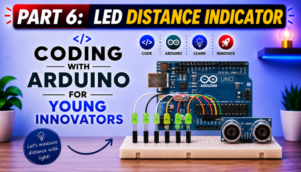
LED Distance Indicator with Ultrasonic Sensor Using Arduino UNO (Complete Tutorial)

Have you ever wondered how a car parking sensor knows when you’re getting too close to an obstacle? One of the simplest ways to understand this technology is by building your own LED Distance Indicator with an HC-SR04 Ultrasonic Sensor and Arduino UNO. In this tutorial, you’ll learn how to create a project that measures the distance to an object and displays that distance visually using a row of 10 LEDs. As an object moves closer to the sensor, more LEDs illuminate. As it moves farther away, the LEDs turn off one by one. This project is ideal for beginners learning Arduino programming, electronics, and sensors. It also introduces concepts that are used in real-world automation and robotics systems. What You Will Learn in This Tutorial By completing this project, you will learn how to: LED Distance Indicator with Ultrasonic Sensor Works The HC-SR04 ultrasonic sensor measures distance by transmitting a burst of ultrasonic sound at 40 kHz. When the sound wave strikes an object, it reflects back towards the sensor. The Arduino measures how long it takes for the echo to return and uses this time to calculate the distance between the sensor and the object. Instead of displaying the measured distance on a screen, this project uses 10 LEDs as a distance indicator. The closer the object is to the sensor, the more LEDs illuminate. For example: This provides a simple visual representation of distance. Components Required You’ll need the following components: Insert Circuit Diagram Here Wiring Connections Connect the components as follows: Component Arduino Pin Remember to connect each LED in series with a 220 Ω resistor to limit current and protect both the LEDs and the Arduino. Understanding the HC-SR04 Ultrasonic Sensor The HC-SR04 has four pins: To measure distance: This process happens in just a few milliseconds. Improving Measurement Accuracy Ultrasonic sensors can occasionally produce slightly different readings due to noise, object shape, or environmental conditions. To improve accuracy, this project measures the distance five times and calculates the average value before updating the LEDs. Averaging multiple readings helps produce smoother and more stable results. Arduino Program Code Explanation The program begins by declaring the Arduino pins connected to the HC-SR04 ultrasonic sensor and the ten LEDs. The LED pins are stored in an array, making it easier to control all the LEDs using loops instead of writing repetitive code. In the setup() function, the trigger pin is configured as an output, the echo pin as an input, and all ten LED pins are set as outputs. Each LED is initially turned off. Inside the loop() function, the Arduino triggers the ultrasonic sensor to send an ultrasonic pulse. The sensor measures how long it takes for the echo to return after reflecting from an object. This process is repeated five times, and the average distance is calculated to provide more stable and accurate readings. The measured distance is then used to determine how many LEDs should be illuminated. If the object is 15 cm or farther, all LEDs remain off. If it is 4 cm or closer, all ten LEDs turn on. For distances between 4 cm and 15 cm, the map() function proportionally converts the distance into the number of LEDs that should light up. Finally, a for loop updates the LEDs by turning on the required number and switching off the rest. This process repeats continuously, creating a real-time visual indicator of the object’s distance from the sensor. Testing the Project After uploading the program: If everything has been wired correctly, the LEDs should respond smoothly to changes in distance. Troubleshooting the LED Distance Indicator with Ultrasonic Sensor If your project does not work as expected, use the troubleshooting tips below to identify and resolve common issues. 1. LEDs Do Not Light Up If none of the LEDs turn on: 2. Sensor Always Reads Zero If the distance remains at zero or no readings are displayed: 3. Distance Readings Fluctuate If the measured distance changes erratically: Real-World Applications LED Distance Indicator with Ultrasonic Sensor Although this is a beginner-friendly Arduino project, the same principle is used in many practical systems, including: Learning this project provides a solid foundation for developing more advanced embedded systems. Conclusion The LED Distance Indicator is an excellent Arduino project for anyone learning electronics and embedded programming. It combines sensor interfacing, digital outputs, and programming logic into a practical application that demonstrates how ultrasonic distance measurement works. By building this project, you gain hands-on experience with the HC-SR04 ultrasonic sensor, learn how to process sensor data, and discover how electronic systems can convert real-world measurements into meaningful visual feedback. Once you’ve mastered this project, you can extend it by replacing the LEDs with an LCD or OLED display, adding a buzzer for audible alerts, or integrating wireless communication for remote monitoring. Watch the Full Video Tutorial Frequently Asked Questions (FAQ) Can I use fewer than 10 LEDs? Yes. Simply modify the program to match the number of LEDs you have available. Why use a 220 Ω resistor with each LED? The resistor limits the current flowing through the LED, helping to protect both the LED and the Arduino output pin. Why average five distance readings? Averaging helps reduce the effect of occasional inaccurate readings, resulting in a more stable LED display. Can this project work with other Arduino boards? Yes. The code can be adapted for other compatible Arduino boards by updating the pin assignments if necessary. What is the measuring range of the HC-SR04? The HC-SR04 typically measures distances from approximately 2 cm to 400 cm, making it suitable for many beginner and intermediate electronics projects. More tutorials Chech other Arduino trutorials we have below:

LED Distance Indicator with Ultrasonic Sensor Using Arduino UNO (Complete Tutorial) Read More »

LED Chaser Circuit project

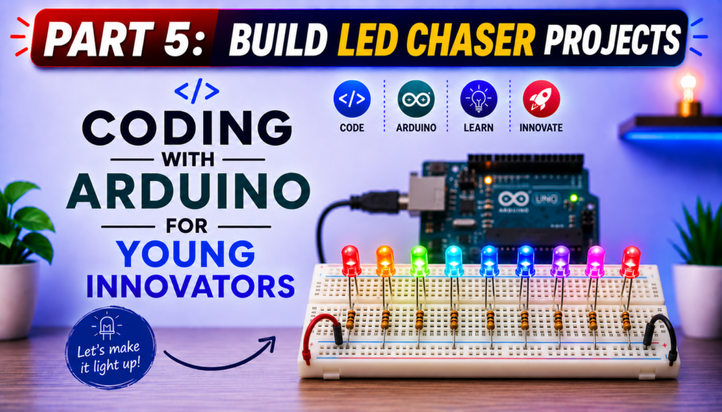
Arduino LED Chaser Circuit Project for Beginners | 6 LED Patterns + Push Button Control

Arduino LED Chaser Circuit Project for Beginners (6 LED Patterns + Bonus Push Button Project) Imagine turning a row of ordinary LEDs into exciting moving light animations with just a few lines of Arduino code. That’s exactly what you’ll build in this tutorial. In this beginner-friendly Arduino project, you’ll learn how to create a fascinating LED Chaser Circuit using an Arduino UNO R3, 10 LEDs, and a breadboard. Instead of simply turning one LED on and off, you’ll control multiple LEDs to create animated lighting effects that move, bounce, and flow across the circuit. By the end of this tutorial, you’ll not only understand how to control multiple LEDs individually but also how to write cleaner Arduino programs using loops, arrays, and functions. We’ll even build a bonus project that uses a push button to switch between six different LED chaser patterns, making the project interactive and much more fun. Whether you’re a child learning Arduino for the first time, a parent teaching STEM at home, a teacher introducing electronics in the classroom, or simply a beginner interested in coding, this project provides an enjoyable way to practice both programming and circuit design. In this guide, you’ll learn: If you’ve already completed our LED Blinking Project, this lesson is the perfect next step because it introduces more advanced programming concepts while still being easy enough for complete beginners to follow. Let’s start by understanding what an LED chaser circuit is and why it’s one of the most popular beginner Arduino projects. What You Will Build By the end of this project, you will have built an exciting Arduino-powered LED chaser capable of displaying six different lighting animations. Each pattern demonstrates a different way of controlling multiple LEDs using code, helping you understand how timing, loops, and digital outputs work together. The bonus feature of this project is a push button that allows you to switch between the different LED patterns without changing or uploading new code. Simply press the button to cycle through the animations and watch your circuit respond instantly. This project is an excellent introduction to creating interactive electronic systems and lays the foundation for more advanced Arduino projects involving displays, motors, sensors, and robotics. Skills You Will Learn After completing this tutorial, you will be able to: What Is an LED Chaser Circuit? An LED chaser circuit is an electronic circuit in which multiple LEDs turn on and off in a programmed sequence, creating the illusion of moving or flowing light. Instead of illuminating all the LEDs at the same time, the lights are activated one after another according to a specific pattern. The movement of the lights is controlled entirely by software running on the Arduino. By changing just a few lines of code, you can create countless lighting effects, from a simple left-to-right chase to more advanced animations that move in opposite directions, bounce back and forth, or light up randomly. An LED chaser is one of the most popular beginner electronics projects because it combines two essential skills: Unlike the basic LED Blink project, where only one LED is controlled, this project introduces multiple digital outputs working together. As a result, you’ll gain a better understanding of how microcontrollers can coordinate several devices simultaneously. How Does an LED Chaser Work? The Arduino UNO controls each LED through one of its digital output pins. When a digital pin is set HIGH, the corresponding LED receives voltage and lights up. When the pin is set LOW, the LED turns off. By rapidly switching different pins on and off in a carefully timed sequence, the Arduino creates the appearance of a moving light. Although only one or a few LEDs may be on at any given moment, the switching happens so quickly that our eyes perceive a smooth animation. The speed of the animation is controlled by the delay() function. Short delays produce fast-moving effects, while longer delays create slower, more noticeable light movements. As you progress through this tutorial, you’ll discover that even simple programming structures, such as for loops, arrays, and functions, can produce surprisingly impressive visual effects. Real-World Applications of LED Chaser Circuits Although this project is designed for learning, the same principles are used in many real-world electronic systems. Understanding how an LED chaser works provides a foundation for designing more advanced control systems in the future. Some common applications include: Many of these systems use the same idea you’re learning here: turning outputs on and off in a carefully timed sequence to create meaningful visual effects. Why This Project Is Great for Beginners The LED Chaser Project builds directly on the skills learned in the LED Blink Project while introducing several important programming concepts without becoming overwhelming. By completing this project, you’ll practice: These are foundational skills you’ll use repeatedly as you move on to more advanced Arduino projects involving LCDs, sensors, motors, robotics, and the Internet of Things (IoT). What You Will Learn in This Tutorial By the end of this guide, you will be able to: These skills will not only help you complete this project but will also prepare you for more advanced Arduino programming challenges in future lessons. Components Required for the Arduino LED Chaser Project Before we start building the circuit, let’s gather all the components you’ll need. One of the best things about this project is that it uses inexpensive, readily available parts, making it perfect for beginners, students, and STEM classrooms. The components used for this project part of the components in out ettronics Coding with Arduino Kit. Unlike the LED Blink Project, which uses just one LED, this tutorial uses 10 LEDs to create exciting lighting animations. Each LED is connected to a separate Arduino digital pin, allowing the microcontroller to control them individually and produce different chasing patterns. The table below lists all the materials required and explains why each one is important. Component Quantity Purpose Arduino UNO R3 1 The microcontroller that controls the LEDs and executes the program. Breadboard 1

Arduino LED Chaser Circuit Project for Beginners | 6 LED Patterns + Push Button Control Read More »

Coding with Arduino for Beginners

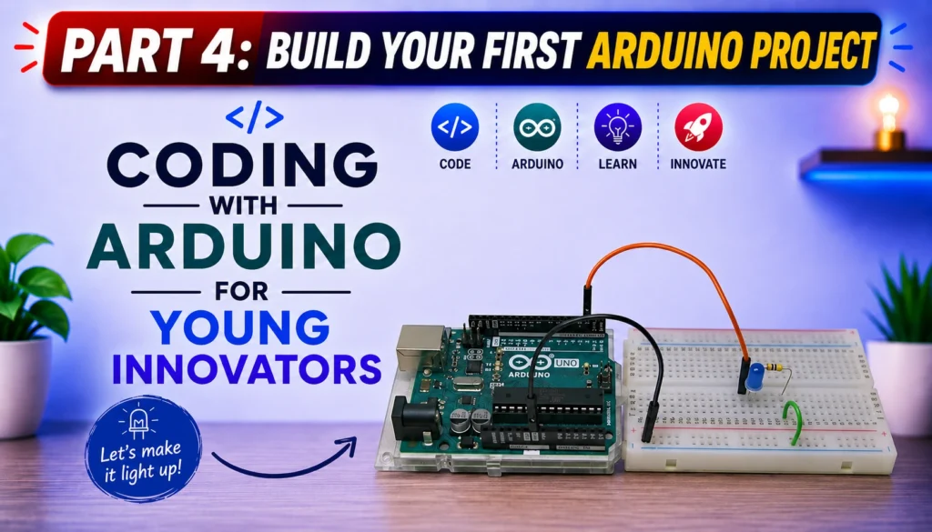
Arduino LED Blink Tutorial for Beginners | Coding with Arduino for Young Innovators

Arduino LED Blink Tutorial for Beginners (Step-by-Step Guide) Learning to program an Arduino is one of the most exciting ways to begin your journey into electronics, robotics, and embedded systems. If you’ve never written a line of code before, don’t worry, this tutorial is designed specifically for beginners, children, parents, teachers, and aspiring innovators who want to learn through practical, hands-on projects. In this lesson, you’ll build one of the most famous beginner projects in electronics: the Arduino LED Blink Project. Although it may seem simple, this project introduces nearly every fundamental concept you’ll use in future Arduino programming, including writing code, uploading programs to a microcontroller, controlling digital outputs, and understanding how a program executes continuously. Whether your goal is to build robots, smart home systems, IoT devices, automation projects, or simply learn programming from scratch, the LED Blink project is the perfect place to start. This tutorial is part of our Coding with Arduino for Young Innovators series, where every lesson builds practical skills through easy-to-understand explanations and exciting projects. Why Every Beginner Starts with the LED Blink Project If you’ve ever searched online for beginner Arduino projects, you’ve probably noticed that almost everyone starts with blinking an LED. That’s not because it’s the easiest project, it’s because it teaches almost every basic programming concept you’ll need later. By completing this project, you’ll learn how to: These skills become the foundation for more advanced projects involving sensors, LCD displays, motors, Bluetooth, Wi-Fi, IoT, and robotics. What You Will Learn By the end of this tutorial, you will understand: If this is your very first Arduino project, you’re in the right place. What Is Arduino? Arduino is an open-source electronics platform that combines both hardware and software to make programming electronic devices simple and accessible. Instead of designing complex electronic circuits from scratch, Arduino provides a programmable microcontroller board that can interact with the outside world. By writing a few lines of code, you can control LEDs, motors, sensors, displays, relays, and many other electronic components. The Arduino platform has become one of the most popular learning tools for: One reason Arduino is so popular is its simplicity. Even someone with no programming experience can build useful projects within a few hours. What Is the Arduino UNO R3? For this lesson, we’re using the Arduino UNO R3, one of the most popular development boards in the world. The Arduino UNO R3 is powered by the ATmega328P microcontroller, which acts as the “brain” of the board. It executes the programs you upload and controls the connected electronic components. Some key features of the Arduino UNO R3 include: These features make the Arduino UNO R3 ideal for learning electronics and programming. As you progress through this course, you’ll use these pins to connect sensors, buzzers, LCDs, ultrasonic modules, Bluetooth devices, Wi-Fi modules, and much more. What Is an LED? An LED (Light Emitting Diode) is a small electronic component that emits light when electrical current flows through it. Unlike ordinary light bulbs, LEDs consume very little power while producing bright light, making them ideal for electronic projects. LEDs come in many colors, including: An LED has two legs: Long Leg (Anode) The longer leg is the positive terminal and should be connected toward the positive voltage through a current-limiting resistor. Short Leg (Cathode) The shorter leg is the negative terminal and is connected to Ground (GND). If you connect the LED backward, it will not light up because LEDs only allow current to flow in one direction. Why Do We Need a Resistor? One of the biggest mistakes beginners make is connecting an LED directly to an Arduino pin. This can allow too much current to flow through the LED, potentially damaging both the LED and the Arduino’s output pin. To prevent this, we use a 220 Ω to 330 Ω resistor in series with the LED. You can check out our resistor calculator software. The resistor limits the current flowing through the LED, ensuring safe operation while maintaining sufficient brightness. Think of the resistor as a traffic controller, it slows the flow of electrical current to a safe level. Components Required To complete this project, you’ll need the following components: Component Quantity Arduino UNO R3 1 Breadboard 1 LED 1 220 Ω or 330 Ω Resistor 1 Jumper Wires 2–3 USB Type A to Type B Cable 1 Computer with Arduino IDE 1 These components are inexpensive and form the basis of countless Arduino projects. Installing the Arduino IDE Before you can program your Arduino UNO R3, you need to install the Arduino Integrated Development Environment (IDE). The Arduino IDE is the software used to write, compile, and upload code to your Arduino board. The Arduino IDE is beginner-friendly and works on Windows, macOS, and Linux. It provides a simple code editor, tools for selecting your board and communication port, and a built-in serial monitor for debugging. Step 1: Download the Arduino IDE Visit the official Arduino website and download the latest version of the Arduino IDE that matches your operating system. Choose the installer for: Once the download is complete, run the installer and follow the on-screen instructions. Step 2: Install the Software After downloading: The installation process usually takes only a few minutes. Connecting the Arduino UNO R3 to Your Computer After installing the Arduino IDE, it’s time to connect your Arduino board. Use a USB Type-A to Type-B cable (often called a printer USB cable). Plug: If everything is connected correctly: Configuring the Arduino IDE Before uploading your program, you must tell the Arduino IDE which board you’re using and which communication port it is connected to. Selecting the Board In the Arduino IDE: This ensures the IDE compiles your code for the correct microcontroller. Selecting the COM Port Next: If you’re unsure which port is correct: Selecting the wrong port will prevent the IDE from uploading your code. Building the LED Blink Circuit Now comes the fun part, building your first electronic circuit. Although the

Arduino LED Blink Tutorial for Beginners | Coding with Arduino for Young Innovators Read More »

Ettronics Hightech Arduino Kit

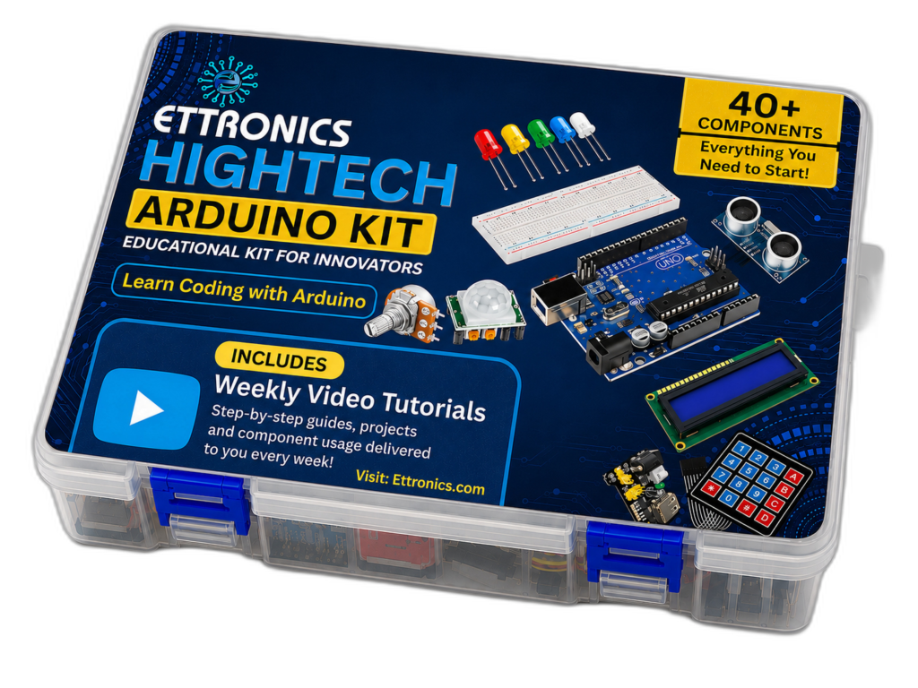
Ettronics Hightech Arduino Kit – Complete Starter Kit with Free Video Tutorials and Technical Support

If you’re looking for the best Arduino starter kit in Nigeria, the Ettronics Hightech Arduino Kit is designed to help you learn Arduino programming, electronics, and embedded systems through practical, hands-on projects. Unlike ordinary Arduino kits that only provide components, the Ettronics Hightech Arduino Kit comes with free step-by-step video tutorials and technical support, making it ideal for complete beginners, students, hobbyists, teachers, and anyone interested in electronics. Why Choose the Ettronics Hightech Arduino Kit? Many beginners purchase an Arduino kit only to discover they don’t know where to start. They are left searching YouTube for random tutorials or trying to understand complex documentation. The Ettronics Hightech Arduino Kit solves this problem by combining quality components with structured learning resources. We provide video lessons that teach you how each component works and how to build real projects from scratch. Whether you’re preparing for a school project, learning robotics, or developing embedded systems skills, this kit provides everything you need to get started. What’s Included in the Arduino Starter Kit? The kit contains over 40 carefully selected components, including: Free Video Tutorials Included One of the biggest advantages of the Ettronics Hightech Arduino Kit is the included video tutorial series. You’ll learn: New tutorials are added regularly, allowing you to continue learning beyond your first project. Technical Support When You Need It Learning electronics can sometimes be challenging. That’s why every customer receives access to technical support. If you encounter difficulties while building a project or understanding a concept, our team is available to guide you. Our goal isn’t just to sell an Arduino kit, it’s to help you become confident in electronics, robotics and embedded systems, Who Is The Ettronics Arduino Kit For? The Ettronics Hightech Arduino Kit is suitable for: No previous programming experience is required. What can you Build with th Ettronics Hightech Arduino Kit? Using the components in the kit, you can build dozens of exciting projects, including: As your skills improve, you’ll be able to combine multiple sensors and modules into more advanced embedded systems. Why Buy from Ettronics Hightech Limited? When you purchase the Ettronics Hightech Arduino Kit, you’re getting more than just hardware. You receive: Start Learning Arduino Today The Ettronics Hightech Arduino Kit makes learning electronics enjoyable, practical, and accessible. Whether your goal is to develop engineering skills, prepare for university projects, build robots, or simply explore embedded systems, this kit provides an excellent foundation. Visit Ettronics Hightech Arduino Kit today to order your Ettronics Hightech Arduino Kit and start building real electronic projects with confidence. You can also check out our Practical Course on on Applied Electronics

Ettronics Hightech Arduino Kit – Complete Starter Kit with Free Video Tutorials and Technical Support Read More »

How to test a transistor using a digital multimeter

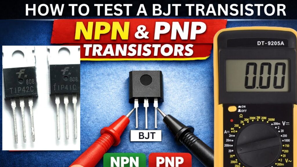
How to Test a Transistor Using a Multimeter (Step-by-Step Beginner Guide)

Have you ever built a circuit, repaired an amplifier, or worked on an electronics project only to discover that it simply refuses to work? In many cases, one small component can be responsible: the transistor. Transistors are among the most commonly used components in electronics, and because they are used as switches and amplifiers in almost every modern circuit, a faulty transistor can stop an entire system from functioning correctly. The good news is that you do not need expensive equipment to test one. A standard digital multimeter can quickly help you determine whether a transistor is healthy or damaged. In this guide, you will learn: Let’s begin. What Is a Transistor? A transistor is a semiconductor device used to control electrical current. It mainly serves two functions: You can think of a transistor as an electronically controlled switch. A small current entering one terminal can control a larger current flowing through the other terminals. Most beginners will commonly encounter two major transistor types: Both types typically have three terminals: Testing either type with a multimeter is relatively similar, although the probe connections differ. Tools Needed Before you begin, gather the following: A digital multimeter with diode mode is highly recommended because it provides more reliable results than continuity mode. Safety Precautions Before Testing Before testing any transistor: Testing a transistor while it remains connected in a circuit may produce incorrect readings because nearby components can affect measurements. Identify the Transistor Pins First Before placing multimeter probes on a transistor, you need to identify its terminals: Different transistors may have different pin arrangements. For example: A TIP41 transistor may use: Pin Function 1 Base 2 Collector 3 Emitter Another transistor may use a different arrangement. The safest approach is checking the transistor datasheet before testing. Understanding Diode Mode on a Multimeter Most digital multimeters have a diode test mode. Diode mode measures the voltage drop across semiconductor junctions. Since a transistor contains two PN junctions internally, testing a transistor in diode mode effectively tests those junctions. For a healthy transistor, typical readings are: How to Test an NPN Transistor Using a Multimeter Watch video below. Follow these steps carefully. Step 1: Set Your Multimeter to Diode Mode Rotate the multimeter dial to diode test mode. Step 2: Connect the Red Probe to the Base Place: Observe the reading. A good transistor should display approximately: 0.5V–0.8V Step 3: Move Black Probe to Collector Keep: Expected reading: 0.5V–0.8V Step 4: Reverse the Probe Connections Now reverse the probes: Expected reading: OL Repeat: Expected reading: OL Step 5: Test Collector to Emitter Measure directly between: Expected reading: OL in both directions If you obtain very low resistance or a short-circuit reading, the transistor is likely damaged. Expected NPN Readings Test Connection Healthy Reading Base → Emitter 0.5V–0.8V Base → Collector 0.5V–0.8V Reverse Base → Emitter OL Reverse Base → Collector OL Collector → Emitter OL How to Test a PNP Transistor Using a Multimeter Testing a PNP transistor is almost identical except that probe polarity changes. Step 1 Set multimeter to diode mode. Step 2 Connect: Expected reading: 0.5V–0.8V Step 3 Keep: Expected reading: 0.5V–0.8V Step 4 Reverse probe connections. Expected reading: OL Expected PNP Readings Test Connection Healthy Reading Base → Emitter 0.5V–0.8V Base → Collector 0.5V–0.8V Reverse Base → Emitter OL Reverse Base → Collector OL Collector → Emitter OL How to Know if a Transistor Is Bad A faulty transistor often produces unusual readings. Signs include: 1. Short Circuit Reading If you measure near zero resistance in both directions: The transistor may be shorted internally. 2. Open Circuit Everywhere If every measurement shows: OL The transistor junctions may be damaged. 3. Collector and Emitter Are Shorted Collector and emitter should not normally behave like a wire. If they do, the transistor is likely defective. 4. Inconsistent Readings Readings that change dramatically each time you test can indicate a damaged transistor. Common Mistakes When Testing a Transistor Many beginners make these mistakes: Testing While the Circuit Is Powered Always disconnect power first. Using Continuity Mode Instead of Diode Mode Continuity mode may not provide accurate transistor measurements. Wrong Pin Identification Incorrectly identifying Base, Collector, or Emitter can produce confusing results. Always verify with the datasheet. Testing While Component Is Still on the Circuit Board Nearby components may interfere with readings. Remove the transistor whenever possible. Frequently Asked Questions Can I test a transistor without removing it from the circuit? Yes, but the readings may not be accurate because surrounding components can affect the measurement. Can a transistor appear good and still fail? Yes. A transistor may pass simple multimeter tests but fail when operating under actual load conditions. Can an analog multimeter test a transistor? Yes. However, digital multimeters are generally easier and more accurate. Can a multimeter identify transistor type automatically? Some multimeters include transistor testing sockets that can automatically identify transistor characteristics. Final Thoughts Knowing how to test a transistor using a multimeter is one of the most useful skills in electronics troubleshooting and repair. Whether you are building DIY projects, repairing devices, or learning electronics for the first time, this simple procedure can save time and prevent unnecessary component replacement. Once you become comfortable testing transistors, the next step is learning how to test other electronic components using the same multimeter. You may also want to read: Mastering these basic troubleshooting skills will make diagnosing electronic circuits much easier and faster. If you want to learn practical electronics circuit design, check out our practical course

How to Test a Transistor Using a Multimeter (Step-by-Step Beginner Guide) Read More »

Analog vs Digital Circuit and more

Difference Between Analog and Digital Electronics with Practical Examples

Generally, every electronic circuit is either an analog circuit or a digital circuit. Analog circuits are often referred to as “Linear” circuits, we shall get to know why as we proceed. In this tutorial, you will learn: The components you need for this tutorial include: You may have seen the speedometer on a car dash board or the speed level graphics on your car race computer game. They are analog systems.  In the car, as you apply pressure on the throttle or accelerator, the speed of the car increases with time and you can view the rate of this increase on your speedometer. Also, in your computer game, as you press the throttle button more, the speed level increases as well. In the two systems, if you reduce the pressure on the throttles, the speed levels go down. Such a system that varies with time is called an analog system. Analog vs digital Electronic Circuit In analog electronic systems, voltage or current is used to represent various physical measurements; like the speed of the car, temperature, humidity, pressure, amount of light, etc. When we want to electronically measure all these physical quantities that vary with time, we do so using an electronic system.  An electronic system will convert these varying physical quantities, to varying voltages or currents that are proportional to the physical quantities being measured. This can be achieved by using analog electronic circuits that contain transducers. Transducers can be sensors, devices or systems that can convert one form of energy to another or one form of system to another. Figure 1 above shows a block diagram of a physical change measurement being converted to voltage or current using an analog electronic circuit. Figure 2 shows an electronic circuit that can convert a varying physical measurement to varying current. The circuit contains a light dependent resistor (LDR). A light dependent resistor is a resistor whose resistance varies with respect to the amount of light shining on it. As the light intensity on the LDR increases, its resistance decreases, and as the light intensity decreases its resistance increases. This constitutes a varying physical system. With the help of an analog electronic circuit, we can measure this varying light intensity in the form of current that flows through a light emitting diode (LED).  When you turn on the switch, and gradually cover the LDR,  the light intensity on the LDR decreases. The resistance of the LDR increases up to 10,000,000Ω = 10MΩ, when this happens, current flow through the LED will gradually reduce in intensity, because the resistance along its path of flow has drastically reduced as a result of the increased resistance of the LDR. But, when you gradually remove your hand from the LDR and have the LDR exposed in such a way that a reasonable amount of light shines on it, the resistance of the LDR will decrease tending to 0Ω. When this happens, the current flow through the LED will see little to no resistance on the LDR, the fixed resistance it will see is the 220Ω resistance of the current limiting resistor, which is there to protect the LED from getting fried from high current. So, as your hand is gradually removed from the LDR, the LED gradually brightens up. If this action of covering and uncovering of the LDR is gradually repeated, the LED will be gradually going ON and OFF. With this analog electronic circuit, we are actually monitoring and tracking light intensity. If we connect an ammeter in series with the LDR, we can measure the intensity of light on the LDR by multiplying the measured current by a factor. To learn how to use a multimeter like a professional, check out our Practical electronics circuit design course for the absolute beginner If we connect a voltmeter across the LDR, we can measure the voltage drop on the LDR. By  multiplying this voltage value by a factor, we can measure the varying intensity of light on the LDR. The bottom line is this: we are tracking a varying physical system (change in light intensity) with varying voltage and current. This electronic circuit that takes in a varying input and in turn produces a varying output is called an analog electronic circuit. But if the system takes in a varying input and produces a steady output, like ON or OFF without a lower value ON (like a LED dimming as in the case above), such an electronic circuit is called a digital electronic circuit. Figure 3 above is a simple LED circuit to explain a digital system. When the switch is pressed, the LED comes ON with a steady brightness and when the switch is turned OFF, the LED goes off. In the event of pressing the switch, the LED is either ON or OFF, there is nothing like lower brightness or higher brightness. The LED having only an OFF or ON state is a typical digital electronic circuit implementation. In digital electronics, no matter the variation of the measured system, the output or result is either 0 or 1, HIGH or LOW, ON or OFF, 5 volts or 0 volts, 3.3 volts or 0 volts. Figure 3 above is similar to figure 2; the only difference is the removal of the LDR from figure 3. In the analog system, the varying brightness of the LED tells us that the system is analog, while in the digital system, the LED only takes two distinct stats, either ON or OFF. Some Components Used to Design Analog Circuits The design of analog electronic circuit requires bunch of discrete components and some integrated circuits (IC) listed below: We discussed most of these components in detail in our practical electronics circuit design course, a course that was created to take you from knowing nothing about electronics circuit design, to mastering the fundamentals of electronics circuit design from scratch. On the other hand, digital electronic circuits are built from logic gate integrated circuits. It’s quite disappointing that some

Difference Between Analog and Digital Electronics with Practical Examples Read More »

Scroll to Top