Learning Arduino programming doesn’t require an expensive laptop or desktop computer. If you have an Android smartphone, you already have a complete portable setup for building, compiling, and uploading code to a microcontroller.
As part of the Coding with Arduino for Young Innovators series (Part 10) using the Ettronics Hightech Arduino kit, this guide walks you through programming an Arduino Uno directly from an Android phone. You will build a basic LED circuit, upload your first program, and modify the code to control how fast the LED blinks.
Prerequisites & Components
All circuit components used in this tutorial are included in the Ettronics Hightech Arduino Kit.
Hardware Requirements:
- Arduino Uno R3 board
- Android Smartphone
- USB OTG Adapter (USB-C included in the Ettronics Arduino Kit)
- USB Cable (Standard USB-A to USB-B Arduino cable – included in the Arduino kit)
- Breadboard
- LED (any of your choice)
- 220Ω Resistor
- Jumper Wires
Software Requirements:
- ArduinoDroid App (Free on Google Play Store)
Step-by-Step Guide
- Download and Install ArduinoDroid App:
- Open the Google Play Store, search for ArduinoDroid, and install the application.
2. Build the LED Circuit:
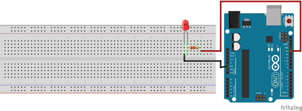
Connect your components as shown in the circuit diagram above
- Place the LED into the breadboard. The longer leg is the positive anode; the shorter leg is the negative cathode.
- Connect a 220Ω resistor from Pin 13 on the Arduino Uno to the anode (long leg) of the LED. The resistor limits current to prevent burning out the LED.
- Connect a jumper wire from the cathode (short leg) of the LED to one of the GND (Ground) pins on the Arduino Uno.
3. Connect Arduino Board to Your Cellphone:
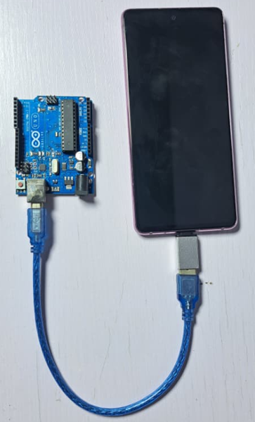
Plug the OTG adapter directly into your Android smartphone’s charging port, Connect the standard USB end into the USB OTG adapter, then plug the USB cable into the Arduino Uno. Once connected, your phone supplies power directly to the Arduino board.
4. Set up the Arduino Board in the Arduinodroid App:
- Open ArduinoDroid, access the Settings menu by clicking the 3 dots on the top right corner, and tap Board Type.
- Select Arduino, then tap Uno from the list of target devices.
5. Load the Blink Example:
Open the app menu and navigate to: Sketch > Examples > Basics > Blink.
The example loads the standard blinking code into the editor:
/*
  Blink

  Turns an LED on for one second, then off for one second, repeatedly.

  Most Arduinos have an on-board LED you can control. On the UNO, MEGA and ZERO
  it is attached to digital pin 13, on MKR1000 on pin 6. LED_BUILTIN is set to
  the correct LED pin independent of which board is used.
  If you want to know what pin the on-board LED is connected to on your Arduino
  model, check the Technical Specs of your board at:
  https://www.arduino.cc/en/Main/Products

  modified 8 May 2014
  by Scott Fitzgerald
  modified 2 Sep 2016
  by Arturo Guadalupi
  modified 8 Sep 2016
  by Colby Newman

  This example code is in the public domain.

  http://www.arduino.cc/en/Tutorial/Blink
*/

// the setup function runs once when you press reset or power the board
void setup() {
  // initialize digital pin LED_BUILTIN as an output.
  pinMode(LED_BUILTIN, OUTPUT);
}

// the loop function runs over and over again forever
void loop() {
  digitalWrite(LED_BUILTIN, HIGH);   // turn the LED on (HIGH is the voltage level)
  delay(1000);                       // wait for a second
  digitalWrite(LED_BUILTIN, LOW);    // turn the LED off by making the voltage LOW
  delay(1000);                       // wait for a second
}
The code above above is what you will see on the Arduinodroid blink example code. It is the same thing as the code below.
void setup() {
  pinMode(13, OUTPUT); // Sets Pin 13 as a digital output
}

void loop() {
  digitalWrite(13, HIGH); // Supplies 5V to Pin 13 (LED turns ON)
  delay(1000);            // Waits for 1,000 milliseconds (1 second)
  digitalWrite(13, LOW);  // Sets Pin 13 to 0V (LED turns OFF)
  delay(1000);            // Waits for 1 second
}
5.Compile and Upload the Code:
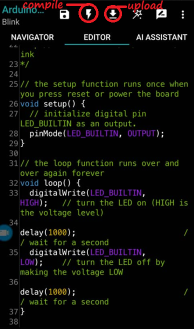
- Tap the Compile icon in ArduinoDroid to convert the C++ code into machine instructions.
- Tap Upload. When prompted by Android for USB device access permissions, tap Allow.
- Once the transfer completes, the LED connected to Pin 13 will begin toggling on and off every second.
Modifying Code & Changing LED Speed
Built-in example sketches are read-only. To experiment with the code:
- Copy the code from the Blink example.
- Tap New Sketch, paste the code, and save it under a new project name.
- Locate the
delay()functions insideloop(). The standarddelay(1000);pauses the execution for 1,000 milliseconds (1 second).
To alter the performance of the circuit, update the delay parameter:
| Code Modification | Delay Duration | LED Behavior |
delay(1000); | 1.0 Second | Standard default blink rate |
delay(500); | 0.5 Seconds | Blinks twice as fast |
delay(100); | 0.1 Seconds | Rapid blinking pulse |
Compile and upload the modified sketch to update the microcontroller instantly.
Key Takeaways
- No PC Required: Android smartphones can power, write, compile, and program hardware via USB OTG adapters and ArduinoDroid.
- Code Controls Hardware: Changing execution parameters inside the code (such as
delay()) instantly dictates physical circuit interactions. - Core Functions:
pinMode()defines pin configurations,digitalWrite()toggles output states, anddelay()sets timing loops.
Frequently Asked Questions
Can I program Arduino using an iPhone?
No. iOS limits raw USB OTG hardware communications required by microcontrollers. This setup relies on Android’s USB host driver capabilities.
Why does the phone ask for USB permission when uploading?
Android protects hardware ports by requiring explicit permission before allowing an application to send hex files over serial data pins to connected microcontrollers.
Do I need an external battery for the Arduino while connected to the phone?
No. The phone’s USB OTG port provides 5V power, which is sufficient to power the Arduino Uno and small components like single LEDs or sensors.
Tutorial video
You can watch the tutorial video for the project below