Have you ever wondered how a car parking sensor knows when you’re getting too close to an obstacle? One of the simplest ways to understand this technology is by building your own LED Distance Indicator with an HC-SR04 Ultrasonic Sensor and Arduino UNO.
In this tutorial, you’ll learn how to create a project that measures the distance to an object and displays that distance visually using a row of 10 LEDs. As an object moves closer to the sensor, more LEDs illuminate. As it moves farther away, the LEDs turn off one by one.
This project is ideal for beginners learning Arduino programming, electronics, and sensors. It also introduces concepts that are used in real-world automation and robotics systems.
What You Will Learn in This Tutorial
By completing this project, you will learn how to:
- Interface the HC-SR04 ultrasonic sensor with an Arduino UNO.
- Measure distance using ultrasonic sound waves.
- Control multiple LEDs from an Arduino.
- Process multiple sensor readings to obtain a more stable measurement.
- Create a simple visual distance indicator.
- Apply Arduino programming concepts such as loops, arrays, functions, and conditional statements.
LED Distance Indicator with Ultrasonic Sensor Works
The HC-SR04 ultrasonic sensor measures distance by transmitting a burst of ultrasonic sound at 40 kHz. When the sound wave strikes an object, it reflects back towards the sensor.
The Arduino measures how long it takes for the echo to return and uses this time to calculate the distance between the sensor and the object.
Instead of displaying the measured distance on a screen, this project uses 10 LEDs as a distance indicator.
The closer the object is to the sensor, the more LEDs illuminate.
For example:
- Object is far away → Only one LED lights.
- Object moves closer → More LEDs illuminate.
- Object is very close → All ten LEDs turn on.
This provides a simple visual representation of distance.
Components Required
You’ll need the following components:
- Arduino UNO
- HC-SR04 Ultrasonic Sensor
- 10 LEDs
- 10 × 220 Ω resistors
- Breadboard
- Jumper wires
- USB cable for programming the Arduino
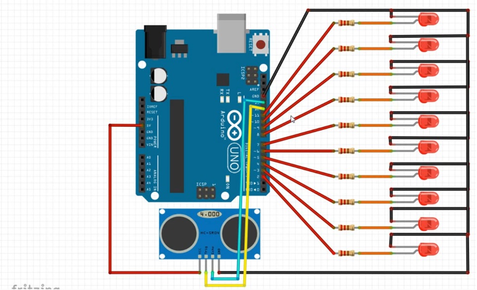
- Circuit Diagram
Insert Circuit Diagram Here
Wiring Connections
Connect the components as follows:
Component Arduino Pin
- LED 1 Pin 2
- LED 2 Pin 3
- LED 3 Pin 4
- LED 4 Pin 5
- LED 5 Pin 6
- LED 6 Pin 7
- LED 7 Pin 8
- LED 8 Pin 9
- LED 9 Pin 10
- LED 10 Pin 11
- HC-SR04 Trigger Pin 12
- HC-SR04 Echo Pin 13
- HC-SR04 VCC 5V
- HC-SR04 GND GND
Remember to connect each LED in series with a 220 Ω resistor to limit current and protect both the LEDs and the Arduino.
Understanding the HC-SR04 Ultrasonic Sensor
The HC-SR04 has four pins:
- VCC – Power supply (5V)
- Trig – Sends the ultrasonic pulse
- Echo – Receives the reflected pulse
- GND – Ground connection
To measure distance:
- The Arduino sends a short trigger pulse.
- The sensor emits ultrasonic waves.
- The waves bounce off nearby objects.
- The echo pin stays HIGH until the reflected sound returns.
- The Arduino measures this time and converts it into distance.
This process happens in just a few milliseconds.
Improving Measurement Accuracy
Ultrasonic sensors can occasionally produce slightly different readings due to noise, object shape, or environmental conditions.
To improve accuracy, this project measures the distance five times and calculates the average value before updating the LEDs.
Averaging multiple readings helps produce smoother and more stable results.
Arduino Program
// Declare pins where the Ultrasonic sensor will be connected
const int trigPin = 12;
const int echoPin = 13;

// Create Array of pins where the LEDs will be connected

const int ledPins[10] = {2, 3, 4, 5, 6, 7, 8, 9, 10, 11};

//Declare variables to store duration and distance
long duration;
float distance;

void setup()
//Set variables to either INPUT or OUTPUT

{
  pinMode(trigPin, OUTPUT);
  pinMode(echoPin, INPUT);

  for (int i = 0; i < 10; i++)
  {
    pinMode(ledPins[i], OUTPUT);
    digitalWrite(ledPins[i], LOW);
  }

}

void loop()
{
  // Measures distance 5 times and calculates the average
  float total = 0;

  for (int i = 0; i < 5; i++)
  {
    digitalWrite(trigPin, LOW);
    delayMicroseconds(2);

    digitalWrite(trigPin, HIGH);
    delayMicroseconds(10);
    digitalWrite(trigPin, LOW);

    duration = pulseIn(echoPin, HIGH, 30000);

    if (duration > 0)
    {
      total += duration * 0.0343 / 2.0;
    }

    delay(5);
  }

  distance = total / 5.0;

  // Determine number of LEDs to turn ON and OFF
  int ledsOn;

  if (distance >= 15)
  {
    ledsOn = 0;
  }
  else if (distance <= 4)
  {
    ledsOn = 10;
  }
  else
  {
    ledsOn = map((int)(distance * 10), 150, 40, 0, 10);
  }

  ledsOn = constrain(ledsOn, 0, 10);

  //Turns LEDs ON or OFF
  for (int i = 0; i < 10; i++)
  {
    if (i < ledsOn)
      digitalWrite(ledPins[i], HIGH);
    else
      digitalWrite(ledPins[i], LOW);
  }

  delay(5);
}
Code Explanation
The program begins by declaring the Arduino pins connected to the HC-SR04 ultrasonic sensor and the ten LEDs. The LED pins are stored in an array, making it easier to control all the LEDs using loops instead of writing repetitive code.
In the setup() function, the trigger pin is configured as an output, the echo pin as an input, and all ten LED pins are set as outputs. Each LED is initially turned off.
Inside the loop() function, the Arduino triggers the ultrasonic sensor to send an ultrasonic pulse. The sensor measures how long it takes for the echo to return after reflecting from an object. This process is repeated five times, and the average distance is calculated to provide more stable and accurate readings.
The measured distance is then used to determine how many LEDs should be illuminated. If the object is 15 cm or farther, all LEDs remain off. If it is 4 cm or closer, all ten LEDs turn on. For distances between 4 cm and 15 cm, the map() function proportionally converts the distance into the number of LEDs that should light up.
Finally, a for loop updates the LEDs by turning on the required number and switching off the rest. This process repeats continuously, creating a real-time visual indicator of the object’s distance from the sensor.
Testing the Project
After uploading the program:
- Power the Arduino.
- Place an object in front of the ultrasonic sensor.
- Slowly move the object closer.
- Observe the LEDs turning on one by one.
- Move the object away again.
- Notice the LEDs turning off in reverse order.
If everything has been wired correctly, the LEDs should respond smoothly to changes in distance.
Troubleshooting the LED Distance Indicator with Ultrasonic Sensor
If your project does not work as expected, use the troubleshooting tips below to identify and resolve common issues.
1. LEDs Do Not Light Up
If none of the LEDs turn on:
- Verify that each LED is connected with the correct polarity (anode and cathode).
- Ensure every LED has a 220 Ω resistor connected in series.
- Confirm that the LEDs are connected to the correct Arduino pins (2–11) as specified in the program.
- Check that all jumper wire connections are secure.
2. Sensor Always Reads Zero
If the distance remains at zero or no readings are displayed:
- Ensure the Trigger and Echo pins are connected to the correct Arduino pins.
- Verify that the sensor’s VCC is connected to the Arduino’s 5V pin and GND to Ground.
- Check that the sensor is not damaged or loosely connected.
3. Distance Readings Fluctuate
If the measured distance changes erratically:
- Check for loose or poor jumper wire connections.
- Ensure the sensor is facing a flat, solid object for better echo reflection.
- Remove any obstacles that may interfere with the ultrasonic signal.
- Take multiple readings and average them, as implemented in this project, to improve measurement stability.
Real-World Applications LED Distance Indicator with Ultrasonic Sensor
Although this is a beginner-friendly Arduino project, the same principle is used in many practical systems, including:
- Car reverse parking assistance
- Robot obstacle detection
- Water tank level monitoring
- Smart waste bin monitoring
- Industrial object detection
- Automated production systems
- Distance warning systems
Learning this project provides a solid foundation for developing more advanced embedded systems.
Conclusion
The LED Distance Indicator is an excellent Arduino project for anyone learning electronics and embedded programming. It combines sensor interfacing, digital outputs, and programming logic into a practical application that demonstrates how ultrasonic distance measurement works.
By building this project, you gain hands-on experience with the HC-SR04 ultrasonic sensor, learn how to process sensor data, and discover how electronic systems can convert real-world measurements into meaningful visual feedback.
Once you’ve mastered this project, you can extend it by replacing the LEDs with an LCD or OLED display, adding a buzzer for audible alerts, or integrating wireless communication for remote monitoring.
Watch the Full Video Tutorial
Frequently Asked Questions (FAQ)
Can I use fewer than 10 LEDs?
Yes. Simply modify the program to match the number of LEDs you have available.
Why use a 220 Ω resistor with each LED?
The resistor limits the current flowing through the LED, helping to protect both the LED and the Arduino output pin.
Why average five distance readings?
Averaging helps reduce the effect of occasional inaccurate readings, resulting in a more stable LED display.
Can this project work with other Arduino boards?
Yes. The code can be adapted for other compatible Arduino boards by updating the pin assignments if necessary.
What is the measuring range of the HC-SR04?
The HC-SR04 typically measures distances from approximately 2 cm to 400 cm, making it suitable for many beginner and intermediate electronics projects.
More tutorials
Chech other Arduino trutorials we have below: