Arduino LED Chaser Circuit Project for Beginners (6 LED Patterns + Bonus Push Button Project)
Imagine turning a row of ordinary LEDs into exciting moving light animations with just a few lines of Arduino code. That’s exactly what you’ll build in this tutorial.
In this beginner-friendly Arduino project, you’ll learn how to create a fascinating LED Chaser Circuit using an Arduino UNO R3, 10 LEDs, and a breadboard. Instead of simply turning one LED on and off, you’ll control multiple LEDs to create animated lighting effects that move, bounce, and flow across the circuit.
By the end of this tutorial, you’ll not only understand how to control multiple LEDs individually but also how to write cleaner Arduino programs using loops, arrays, and functions. We’ll even build a bonus project that uses a push button to switch between six different LED chaser patterns, making the project interactive and much more fun.
Whether you’re a child learning Arduino for the first time, a parent teaching STEM at home, a teacher introducing electronics in the classroom, or simply a beginner interested in coding, this project provides an enjoyable way to practice both programming and circuit design.
In this guide, you’ll learn:
- How an LED chaser circuit works
- How to connect 10 LEDs to an Arduino UNO R3
- Why every LED needs a current-limiting resistor
- How to write Arduino code that controls multiple LEDs
- How to create six different LED animation patterns
- How to use a push button to switch between patterns
- Common mistakes beginners make and how to avoid them
If you’ve already completed our LED Blinking Project, this lesson is the perfect next step because it introduces more advanced programming concepts while still being easy enough for complete beginners to follow.
Let’s start by understanding what an LED chaser circuit is and why it’s one of the most popular beginner Arduino projects.
What You Will Build
By the end of this project, you will have built an exciting Arduino-powered LED chaser capable of displaying six different lighting animations. Each pattern demonstrates a different way of controlling multiple LEDs using code, helping you understand how timing, loops, and digital outputs work together.
The bonus feature of this project is a push button that allows you to switch between the different LED patterns without changing or uploading new code. Simply press the button to cycle through the animations and watch your circuit respond instantly.
This project is an excellent introduction to creating interactive electronic systems and lays the foundation for more advanced Arduino projects involving displays, motors, sensors, and robotics.
Skills You Will Learn
After completing this tutorial, you will be able to:
- Build a multi-LED circuit on a breadboard.
- Connect and control 10 LEDs using an Arduino UNO R3.
- Understand why resistors are necessary in LED circuits.
- Write Arduino programs that control multiple outputs efficiently.
- Use arrays and
forloops to reduce repetitive code. - Create smooth LED animation effects.
- Read input from a push button.
- Design interactive Arduino projects with multiple operating modes.
- Improve your debugging skills when working with electronic circuits.
What Is an LED Chaser Circuit?
An LED chaser circuit is an electronic circuit in which multiple LEDs turn on and off in a programmed sequence, creating the illusion of moving or flowing light. Instead of illuminating all the LEDs at the same time, the lights are activated one after another according to a specific pattern.
The movement of the lights is controlled entirely by software running on the Arduino. By changing just a few lines of code, you can create countless lighting effects, from a simple left-to-right chase to more advanced animations that move in opposite directions, bounce back and forth, or light up randomly.
An LED chaser is one of the most popular beginner electronics projects because it combines two essential skills:
- Circuit building – learning how to connect multiple electronic components correctly.
- Programming – learning how to control hardware using Arduino code.
Unlike the basic LED Blink project, where only one LED is controlled, this project introduces multiple digital outputs working together. As a result, you’ll gain a better understanding of how microcontrollers can coordinate several devices simultaneously.
How Does an LED Chaser Work?
The Arduino UNO controls each LED through one of its digital output pins. When a digital pin is set HIGH, the corresponding LED receives voltage and lights up. When the pin is set LOW, the LED turns off.
By rapidly switching different pins on and off in a carefully timed sequence, the Arduino creates the appearance of a moving light. Although only one or a few LEDs may be on at any given moment, the switching happens so quickly that our eyes perceive a smooth animation.
The speed of the animation is controlled by the delay() function. Short delays produce fast-moving effects, while longer delays create slower, more noticeable light movements.
As you progress through this tutorial, you’ll discover that even simple programming structures, such as for loops, arrays, and functions, can produce surprisingly impressive visual effects.
Real-World Applications of LED Chaser Circuits
Although this project is designed for learning, the same principles are used in many real-world electronic systems. Understanding how an LED chaser works provides a foundation for designing more advanced control systems in the future.
Some common applications include:
- Decorative lighting displays
- Holiday and festive light animations
- Advertising and shop signage
- Emergency vehicle warning lights
- Automotive sequential turn indicators
- Electronic toys and games
- Stage and event lighting
- Industrial status indicators
- Robotics projects
- Interactive STEM demonstrations
Many of these systems use the same idea you’re learning here: turning outputs on and off in a carefully timed sequence to create meaningful visual effects.
Why This Project Is Great for Beginners
The LED Chaser Project builds directly on the skills learned in the LED Blink Project while introducing several important programming concepts without becoming overwhelming.
By completing this project, you’ll practice:
- Controlling multiple digital output pins.
- Building larger circuits on a breadboard.
- Organizing code for readability.
- Using repetition efficiently instead of writing the same instructions many times.
- Creating animations through precise timing.
- Making projects interactive using a push button.
These are foundational skills you’ll use repeatedly as you move on to more advanced Arduino projects involving LCDs, sensors, motors, robotics, and the Internet of Things (IoT).
What You Will Learn in This Tutorial
By the end of this guide, you will be able to:
- Build a 10-LED chaser circuit on a breadboard.
- Connect each LED safely using the correct resistor.
- Program an Arduino UNO R3 to control multiple LEDs.
- Create six unique LED chaser animations.
- Use a push button to switch between lighting patterns.
- Understand how timing affects LED animations.
- Write cleaner Arduino code using loops and arrays.
- Troubleshoot common wiring and programming mistakes.
These skills will not only help you complete this project but will also prepare you for more advanced Arduino programming challenges in future lessons.
Components Required for the Arduino LED Chaser Project
Before we start building the circuit, let’s gather all the components you’ll need. One of the best things about this project is that it uses inexpensive, readily available parts, making it perfect for beginners, students, and STEM classrooms. The components used for this project part of the components in out ettronics Coding with Arduino Kit.
Unlike the LED Blink Project, which uses just one LED, this tutorial uses 10 LEDs to create exciting lighting animations. Each LED is connected to a separate Arduino digital pin, allowing the microcontroller to control them individually and produce different chasing patterns.
The table below lists all the materials required and explains why each one is important.
| Component | Quantity | Purpose |
|---|---|---|
| Arduino UNO R3 | 1 | The microcontroller that controls the LEDs and executes the program. |
| Breadboard | 1 | Allows you to build the circuit without soldering. |
| LEDs (Any Color) | 10 | Produce the various lighting patterns and animations. |
| 220 Ω Resistors | 10 | Limit the current through each LED to protect it from damage. |
| Push Button | 1 | Used in the bonus project to switch between LED patterns. |
| Jumper Wires | Several | Connect the Arduino to the breadboard and components. |
| USB Type-A to Type-B Cable | 1 | Powers the Arduino and uploads the program. |
| Computer with Arduino IDE | 1 | Used to write, edit, compile, and upload the Arduino sketch. |
Understanding Each Component
Arduino UNO R3
The Arduino UNO R3 is the brain of this project. It receives the program you write in the Arduino IDE and controls each LED by sending HIGH and LOW signals through its digital output pins.
Every lighting effect you see, from simple left-to-right movement to more advanced animations, is generated by the Arduino following the instructions in your code.
Because the Arduino UNO is beginner-friendly, widely supported, and inexpensive, it is one of the best boards for learning electronics and programming.
Breadboard
The breadboard allows you to assemble electronic circuits without soldering.
Its internal metal strips connect rows of holes together, making it easy to insert components, move them around, and experiment with different circuit designs.
Using a breadboard also makes troubleshooting much easier because components can be removed and replaced in seconds.
LEDs
An LED (Light Emitting Diode) is a semiconductor device that emits light when current flows through it.
In this project, we use 10 LEDs arranged in a row to create animated lighting effects.
You may use:
- Red LEDs
- Green LEDs
- Blue LEDs
- Yellow LEDs
- White LEDs
- Or a mixture of different colors for a more colorful display
Remember that LEDs are polarized components, meaning they have a positive and a negative terminal.
- Long leg (Anode): Connects toward the Arduino output through a resistor.
- Short leg (Cathode): Connects to the Arduino GND (Ground).
If an LED is inserted backwards, it simply will not light up.
220 Ω Resistors
Every LED in this project requires its own 220-ohm resistor.
The resistor limits the amount of current flowing through the LED, preventing excessive current that could permanently damage both the LED and the Arduino output pin.
A common beginner mistake is connecting an LED directly to an Arduino pin without a resistor. While the LED may light briefly, doing so can shorten its lifespan or damage the LED.
For this reason, always use one resistor per LED.
Safety Tip: Never connect an LED directly to an Arduino digital pin without a current-limiting resistor.
Push Button
The push button is used in the bonus section of this project.
Instead of uploading a different sketch for each LED animation, you’ll be able to press the button to switch between six different lighting patterns while the Arduino continues running the same program.
This introduces an important programming concept called user input, where the Arduino responds to actions performed by the user.
Jumper Wires
Jumper wires provide the electrical connections between the Arduino, breadboard, LEDs, resistors, and push button.
Using different wire colors helps keep the circuit organized. A common convention is:
- Red: Positive voltage (5V)
- Black: Ground (GND)
- Other colors: Signal connections between the Arduino and components
Keeping the wiring neat makes it easier to identify mistakes and troubleshoot the circuit.
USB Cable
The USB Type-A to Type-B cable has two important jobs:
- It powers the Arduino UNO R3.
- It transfers your Arduino sketch from the computer to the board.
Once the code is uploaded, the Arduino begins executing the program immediately.
Computer with Arduino IDE
The Arduino IDE is the software used to write, compile, and upload your program.
It also includes a Serial Monitor, which is useful for debugging and displaying information while developing more advanced Arduino projects.
If you have not installed the Arduino IDE yet, make sure to do so before beginning this tutorial. You can go through this tutorial to guide you on how to install the Arduino IDE.
Why Do We Need 10 Separate Resistors?
One question beginners often ask is:
“Can I use just one resistor for all ten LEDs?”
The answer is no.
Each LED must have its own current-limiting resistor because every LED is controlled independently by the Arduino. Using a single resistor for multiple LEDs can result in uneven brightness, unpredictable behavior, or excessive current flowing through some LEDs.
Providing each LED with its own resistor ensures:
- Consistent brightness across all LEDs.
- Better protection for the Arduino’s output pins.
- Longer LED lifespan.
- Reliable operation of all lighting patterns.
This simple design practice is used in professional electronic circuits and is a habit worth developing from the very beginning.
Before We Start Building…
Now that you have all the required components, it’s time to assemble the LED chaser circuit on the breadboard.
Circuit Diagram and Pin Connections
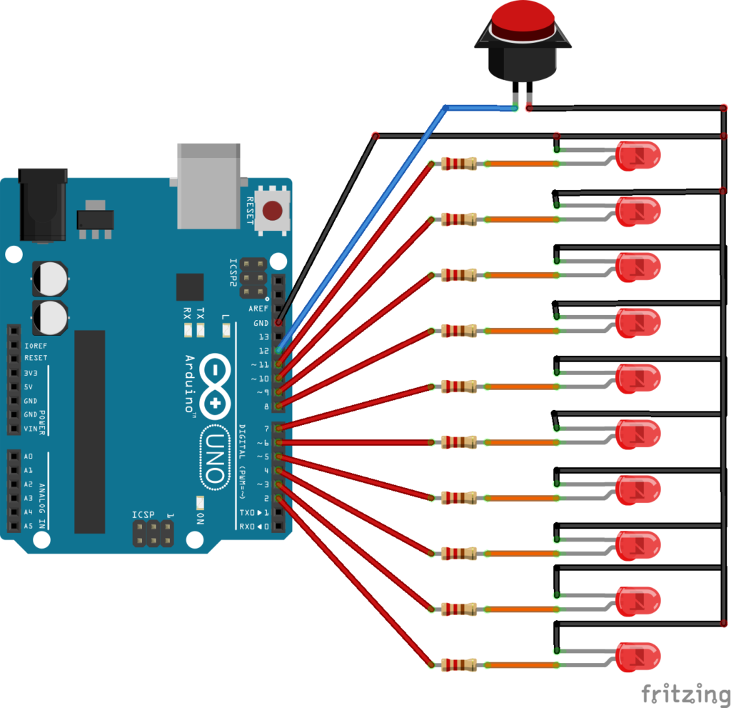
Now that you’ve gathered all the required components, it’s time to build the LED chaser circuit. Don’t worry if this is your first time connecting multiple LEDs to an Arduino board, the wiring is straightforward and follows the same principle for each LED.
Each LED is connected to a separate digital output pin on the Arduino UNO R3 through its own 220 Ω current-limiting resistor. This allows the Arduino to control every LED independently, making it possible to create different lighting animations and chaser effects.
The push button used in the bonus project is connected to digital pin D12 and allows you to switch between the six LED patterns without uploading a new program.
Tip: Before powering the circuit, double-check every connection. A single misplaced jumper wire or a reversed LED can prevent the project from working correctly.
Arduino Pin Connections
The table below shows the exact wiring used in this project.
| Arduino Pin | Connected Component |
|---|---|
| D2 | LED 1 (through 220 Ω resistor) |
| D3 | LED 2 (through 220 Ω resistor) |
| D4 | LED 3 (through 220 Ω resistor) |
| D5 | LED 4 (through 220 Ω resistor) |
| D6 | LED 5 (through 220 Ω resistor) |
| D7 | LED 6 (through 220 Ω resistor) |
| D8 | LED 7 (through 220 Ω resistor) |
| D9 | LED 8 (through 220 Ω resistor) |
| D10 | LED 9 (through 220 Ω resistor) |
| D11 | LED 10 (through 220 Ω resistor) |
| D12 | Push Button |
| GND | Common ground for all LEDs and the push button |
Step-by-Step Wiring Instructions
Follow these steps carefully to assemble the circuit.
Step 1: Position the Arduino and Breadboard
Place the Arduino UNO R3 beside the breadboard, leaving enough space to connect the jumper wires comfortably.
Step 2: Connect the Ground Rail
Run a jumper wire from one of the Arduino’s GND pins to the blue (negative) rail of the breadboard.
This creates a common ground that all ten LEDs and the push button will share.
Step 3: Insert the LEDs
Insert the ten LEDs into the breadboard in a straight line.
Make sure all the long legs (anodes) face the side that will connect to the Arduino pins through the resistors, while all the short legs (cathodes) face the ground rail.
Keeping the LEDs aligned neatly will make the finished project look cleaner and make troubleshooting much easier.
Step 4: Add the Current-Limiting Resistors
Connect one 220 Ω resistor in series with each LED.
One end of the resistor connects to the LED’s anode, while the other end will connect to the appropriate Arduino digital pin.
Each LED must have its own resistor.
Step 5: Connect the Arduino Output Pins
Using jumper wires, make the following connections:
- D2 → LED 1
- D3 → LED 2
- D4 → LED 3
- D5 → LED 4
- D6 → LED 5
- D7 → LED 6
- D8 → LED 7
- D9 → LED 8
- D10 → LED 9
- D11 → LED 10
Each wire carries the HIGH and LOW signals from the Arduino to its corresponding LED.
Step 6: Connect the Push Button
Insert the push button across the center gap of the breadboard.
Connect one side of the button to digital pin D12 and the other side to ground (GND).
In the Arduino program, we’ll configure this pin using the internal pull-up resistor, eliminating the need for an external resistor and simplifying the circuit.
Step 7: Connect the USB Cable
Finally, connect the Arduino UNO R3 to your computer using the USB cable.
The board will receive power, and you’ll be ready to upload the Arduino sketch.
How the Circuit Works
Although the circuit contains ten LEDs, the Arduino controls each one independently.
Whenever the program sets a digital pin to HIGH, the corresponding LED receives voltage and lights up. When the pin is set to LOW, the LED turns off.
By turning different LEDs on and off in carefully timed sequences, the Arduino creates the illusion of moving light. This technique is known as persistence of vision, where the human eye blends rapid changes into smooth motion.
For example, a simple left-to-right sequence might look like this:
LED 1 → LED 2 → LED 3 → LED 4 → LED 5 → LED 6 → LED 7 → LED 8 → LED 9 → LED 10Because each LED lights for only a brief moment before the next one turns on, your eyes perceive a flowing animation rather than ten separate flashes.
The bonus push button makes the project even more interactive. Instead of reprogramming the Arduino each time you want a different effect, pressing the button tells the Arduino to switch to the next LED pattern stored in the program. This demonstrates how a microcontroller can respond to user input while continuing to control multiple outputs.
Beginner Tips Before Uploading the Code
Before opening the Arduino IDE, take a few moments to inspect your circuit.
✔ Every LED has its own 220 Ω resistor.
✔ All LED short legs (cathodes) are connected to GND.
✔ All LED long legs (anodes) are connected to the correct Arduino digital pins.
✔ The push button is connected to D12 and GND.
✔ No jumper wires are loose.
✔ The Arduino is connected to the computer with a USB cable.
A careful inspection now can save you time troubleshooting later.
The Six LED Chaser Patterns You Will Build
One of the most exciting aspects of this project is that you won’t build just one LED animation, you’ll create six unique LED chaser patterns, each demonstrating a different programming technique.
Every pattern uses the same hardware. The only thing that changes is the Arduino program controlling the LEDs. This shows the true power of programming: the same circuit can produce completely different behaviors simply by changing the software.
Let’s take a look at each pattern before diving into the code.
Pattern 1: Fill and Empty
The first animation gradually turns the LEDs on from left to right until all ten LEDs are illuminated.
Once every LED is on, the Arduino turns them off in the same order, creating a smooth filling and emptying effect.
This pattern introduces an important programming concept known as sequential control, where the Arduino performs the same action repeatedly while changing only the LED being controlled.
It is one of the easiest LED animations to understand and serves as an excellent introduction to loops.
What you’ll learn from this pattern:
- Controlling multiple LEDs in sequence.
- Using
forloops. - Understanding timing with
delay(). - Writing clean, repetitive code.
Pattern 2: Running Light
Instead of lighting every LED, this pattern keeps only one LED on at a time.
The illuminated LED appears to travel smoothly from one end of the row to the other, creating the familiar “running light” effect often seen on decorative lighting and electronic displays.
To achieve this effect, the Arduino turns all LEDs off before lighting the next LED in the sequence.
This demonstrates how quickly switching outputs can create smooth visual motion.
Programming concepts introduced:
- Clearing previous outputs.
- Moving a single active LED.
- Reusing functions to simplify code.
Pattern 3: Odd and Even Flash
This animation divides the LEDs into two groups.
First, all the LEDs in the odd-numbered positions illuminate while the others remain off.
Next, the pattern reverses, causing the even-numbered LEDs to light while the odd-numbered LEDs switch off.
The alternating flashes create an attractive visual rhythm while introducing conditional programming.
In this pattern, you’ll learn how mathematical operations such as the modulus operator (%) can be used to separate LEDs into different groups.
Skills you’ll learn:
- Using conditions (
ifstatements). - Understanding odd and even numbers in programming.
- Creating grouped lighting effects.
Pattern 4: Knight Rider
One of the most recognizable LED animations is the classic Knight Rider scanner effect.
A single illuminated LED travels from left to right before reversing direction and sweeping back toward the starting point.
Instead of restarting at the beginning, the animation bounces continuously between both ends of the LED row.
This introduces reverse counting and directional movement.
Many emergency warning lights and decorative displays use similar programming techniques.
Programming concepts introduced:
- Forward loops.
- Reverse loops.
- Direction changes.
- Continuous animation.
Pattern 5: Center Explosion
This pattern creates the illusion of light exploding outward from the middle of the LED row.
The two center LEDs illuminate first.
Next, the LEDs immediately beside them turn on.
The animation continues expanding outward until all ten LEDs are illuminated.
The result resembles an expanding burst of light.
This project demonstrates that LED animations do not always have to begin at one end of the circuit.
Instead, they can originate from any position.
Skills introduced:
- Calculating center positions.
- Controlling multiple LEDs simultaneously.
- Symmetrical programming.
Pattern 6: Inward Chase
The final animation is the opposite of the previous one.
Instead of beginning at the center, the LEDs start at both ends of the row and move toward the middle.
Each step lights two LEDs simultaneously until the center is reached.
This creates a smooth inward movement that appears both balanced and visually appealing.
The animation demonstrates how two different sections of an array can be controlled at exactly the same time.
Programming concepts introduced:
- Working from opposite ends of an array.
- Simultaneous output control.
- Symmetrical animations.
- Advanced indexing techniques.
Bonus Project: Push-Button Pattern Selector
After creating the six individual LED chaser patterns, we’ll combine them into a single Arduino program.
Instead of uploading a different sketch every time you want to change the animation, you’ll use a push button connected to digital pin D12 to cycle through all six patterns instantly.
Each press of the button tells the Arduino to load the next animation, turning the project into an interactive LED pattern generator.
This bonus project introduces several important concepts used in real-world embedded systems:
- Reading digital inputs.
- Detecting button presses.
- Switching between multiple operating modes.
- Organizing larger Arduino programs using functions.
- Using non-blocking programming with
millis()for responsive operation.
This is a significant step beyond simple beginner projects and gives you a taste of how professional embedded systems are designed.
Arduino Program for the LED Chaser Circuit
Now that the hardware is complete, it’s time to bring the circuit to life by writing the Arduino program.
Programming is what transforms this collection of LEDs, resistors, and wires into an exciting interactive project. Although the hardware remains exactly the same, changing the program allows the LEDs to perform completely different animations.
In this project, we create six different LED chaser patterns before combining them into a single program that allows you to switch between the patterns using a push button.
Don’t worry if you’re new to programming. We’ll explain each part of the code in a simple, beginner-friendly manner.
Understanding the Arduino Program Structure
Every Arduino program, also known as a sketch, contains two essential functions:
void setup()
{

}

void loop()
{

}
These two functions are required in every Arduino sketch.
The setup() Function
The setup() function runs only once when the Arduino is powered on or after the Reset button is pressed.
Its purpose is to prepare the Arduino before the main program starts running.
Typical tasks performed inside setup() include:
- Configuring input and output pins.
- Starting serial communication.
- Initializing displays.
- Initializing sensors.
- Setting the initial state of outputs.
In this project, the setup() function tells the Arduino that each LED pin will be used as an output.
The loop() Function
After setup() finishes executing, the Arduino repeatedly executes the loop() function.
Unlike setup(), which runs only once, the loop() function runs continuously until the Arduino is switched off.
Everything that creates the LED animations happens inside this function.
The Arduino repeats the instructions thousands of times, allowing the lighting patterns to continue indefinitely.
Declaring the LED Pins
One of the first things you’ll notice in the program is the following statement:
const byte leds[] = {2,3,4,5,6,7,8,9,10,11};
const byte NUM_LEDS = 10;
This is one of the cleanest parts of the program because it avoids writing ten separate variables.
Instead of writing:
int led1 = 2;
int led2 = 3;
int led3 = 4;
and continuing all the way to LED 10, we store every pin number inside an array.
An array is simply a collection of related values stored under one name.
Here, the array named leds stores the Arduino pin numbers used by all ten LEDs.
| Array Position | Arduino Pin |
|---|---|
| 0 | D2 |
| 1 | D3 |
| 2 | D4 |
| 3 | D5 |
| 4 | D6 |
| 5 | D7 |
| 6 | D8 |
| 7 | D9 |
| 8 | D10 |
| 9 | D11 |
This approach makes the program:
- Easier to read.
- Easier to maintain.
- Easier to modify.
- Much shorter.
It also allows us to control every LED using loops instead of repeating almost identical lines of code.
Understanding NUM_LEDS
Immediately below the array is another constant:
const byte NUM_LEDS = 10;Rather than typing the number 10 throughout the program, we give it a meaningful name.
This improves readability because the code clearly communicates that the value represents the number of LEDs in the project.
It also makes future modifications much easier.
For example, if you later decide to build a 16-LED chaser, you only need to update this value and the array instead of searching through the entire program.
Configuring the Output Pins
Inside the setup() function, we find the following code:
for(int i = 0; i < NUM_LEDS; i++)
{
    pinMode(leds[i], OUTPUT);
}
This is an example of a for loop, one of the most powerful programming tools in Arduino.
Instead of writing ten separate pinMode() statements like this:
pinMode(2, OUTPUT);
pinMode(3, OUTPUT);
pinMode(4, OUTPUT);
...
pinMode(11, OUTPUT);
the for loop performs the same task automatically.
Let’s examine it step by step.
int i = 0
This creates a variable named i and starts counting from 0.
Remember that arrays begin at index 0, not 1.
i < NUM_LEDS
This tells the Arduino to continue repeating the loop while i is less than 10.
i++
This increases the value of i by one after each repetition.
The values become:
0
1
2
3
4
5
6
7
8
9
pinMode(leds[i], OUTPUT);
During each repetition, the Arduino reads the corresponding pin number from the leds array and configures it as an output.
This means the loop automatically executes:
pinMode(2, OUTPUT);
pinMode(3, OUTPUT);
pinMode(4, OUTPUT);
...
pinMode(11, OUTPUT);
without requiring you to write each line individually.
This is a perfect example of how programming can reduce repetitive work and make your code more efficient.
Why Arrays and Loops Are So Important
Imagine that your project had 100 LEDs instead of just 10.
Without arrays and loops, you would need to write hundreds of nearly identical lines of code.
Using arrays together with loops allows the Arduino to repeat tasks automatically, resulting in programs that are shorter, cleaner, easier to understand, and much easier to maintain.
These concepts are widely used not only in Arduino programming but also in professional software development, robotics, automation, embedded systems, and Internet of Things (IoT) applications.
All Codes
Pattern 1: Fill and Empty
// PATTERN 1: Fill and Empty
// LEDs turn ON one by one, then OFF one by one

const byte leds[] = {2,3,4,5,6,7,8,9,10,11};
const byte NUM_LEDS = 10;  // Number of LEDs

void setup() {
  // Set all LED pins as OUTPUT
  for(int i = 0; i < NUM_LEDS; i++) {
    pinMode(leds[i], OUTPUT);
  }
}

void loop() {
  int speed = 80;  // Speed of the effect (lower = faster)

  // FILL: Turn LEDs ON from left to right
  for(int i = 0; i < NUM_LEDS; i++) {
    digitalWrite(leds[i], HIGH);
    delay(speed);
  }

  // EMPTY: Turn LEDs OFF from left to right
  for(int i = 0; i < NUM_LEDS; i++) {
    digitalWrite(leds[i], LOW);
    delay(speed);
  }
}
The Fill and Empty pattern is the first animation in this project. It gradually turns the LEDs on from left to right until all ten LEDs are illuminated. Once they are all on, the Arduino turns them off in the same order, creating a smooth filling and emptying effect.
The program uses a for loop to light each LED one after another.
The digitalWrite() function turns on the current LED, while the delay() function controls how quickly the animation progresses. After all the LEDs have turned on, a second loop switches them off using the same sequence.
Pattern 2: Running Light
// PATTERN 2: Running Light
// A single LED moves from left to right

const byte leds[] = {2,3,4,5,6,7,8,9,10,11};
const byte NUM_LEDS = 10;  // Number of LEDs

void setup() {
  // Set all LED pins as OUTPUT
  for(int i = 0; i < NUM_LEDS; i++) {
    pinMode(leds[i], OUTPUT);
  }
}

// Turn all LEDs OFF
void clearAll() {
  for(int i = 0; i < NUM_LEDS; i++) {
    digitalWrite(leds[i], LOW);
  }
}

void loop() {
  int speed = 70;  // Speed of the running light

  // Move the light from left to right
  for(int i = 0; i < NUM_LEDS; i++) {
    clearAll();                    // Turn all off first
    digitalWrite(leds[i], HIGH);   // Turn on current LED
    delay(speed);                  // Wait before moving
  }
}
In this pattern, only one LED is on at any given time. The illuminated LED moves from the first LED to the last, creating the familiar running-light effect often seen in decorative lighting.
Before turning on the next LED, the program calls a helper function named clearAll(), which switches off every LED. This ensures that only one LED remains lit during the animation.
Pattern 3: Odd and Even Flash
// PATTERN 3: Odd and Even Flash
// Even LEDs flash, then Odd LEDs flash

const byte leds[] = {2,3,4,5,6,7,8,9,10,11};
const byte NUM_LEDS = 10;  // Number of LEDs

void setup() {
  // Set all LED pins as OUTPUT
  for(int i = 0; i < NUM_LEDS; i++) {
    pinMode(leds[i], OUTPUT);
  }
}

void loop() {
  int speed = 200;  // How long each group stays ON

  // Repeat the flash 4 times
  for(int repeat = 0; repeat < 4; repeat++) {

    // Turn ON even LEDs (0,2,4,6,8)
    // Turn OFF odd LEDs (1,3,5,7,9)
    for(int i = 0; i < NUM_LEDS; i++) {
      if(i % 2 == 0) {
        digitalWrite(leds[i], HIGH);  // Even = ON
      } else {
        digitalWrite(leds[i], LOW);   // Odd = OFF
      }
    }
    delay(speed);

    // Turn ON odd LEDs (1,3,5,7,9)
    // Turn OFF even LEDs (0,2,4,6,8)
    for(int i = 0; i < NUM_LEDS; i++) {
      if(i % 2 != 0) {
        digitalWrite(leds[i], HIGH);  // Odd = ON
      } else {
        digitalWrite(leds[i], LOW);   // Even = OFF
      }
    }
    delay(speed);
  }
}
This animation divides the LEDs into two groups. The LEDs in one group light up while the others remain off. After a short delay, the groups swap, producing an alternating flashing effect.
The program uses the modulus (%) operator to determine whether an LED belongs to the odd or even group.
Pattern 4: Knight Rider
// PATTERN 4: Knight Rider
// LED sweeps back and forth like KITT's scanner

const byte leds[] = {2,3,4,5,6,7,8,9,10,11};
const byte NUM_LEDS = 10;  // Number of LEDs

void setup() {
  // Set all LED pins as OUTPUT
  for(int i = 0; i < NUM_LEDS; i++) {
    pinMode(leds[i], OUTPUT);
  }
}

// Turn all LEDs OFF
void clearAll() {
  for(int i = 0; i < NUM_LEDS; i++) {
    digitalWrite(leds[i], LOW);
  }
}

void loop() {
  int speed = 50;  // Speed of the sweeping light

  // Sweep from LEFT to RIGHT
  for(int i = 0; i < NUM_LEDS; i++) {
    clearAll();                    // Turn all off
    digitalWrite(leds[i], HIGH);   // Light up current position
    delay(speed);
  }

  // Sweep from RIGHT to LEFT
  // Start at 8 (skip last LED) and go down to 1 (skip first LED)
  for(int i = NUM_LEDS - 2; i > 0; i--) {
    clearAll();                    // Turn all off
    digitalWrite(leds[i], HIGH);   // Light up current position
    delay(speed);
  }
}
The Knight Rider pattern creates a sweeping light that moves from left to right and then reverses direction, just like the scanner seen on the famous KITT car from the Knight Rider television series.
The Arduino first counts forward through the LED array and then counts backward, creating a continuous back-and-forth animation.
Pattern 5: Center Explosion
// PATTERN 5: Center Explosion
// Lights spread outward from the middle

const byte leds[] = {2,3,4,5,6,7,8,9,10,11};
const byte NUM_LEDS = 10;  // Number of LEDs

void setup() {
  // Set all LED pins as OUTPUT
  for(int i = 0; i < NUM_LEDS; i++) {
    pinMode(leds[i], OUTPUT);
  }
}

// Turn all LEDs OFF
void clearAll() {
  for(int i = 0; i < NUM_LEDS; i++) {
    digitalWrite(leds[i], LOW);
  }
}

void loop() {
  int speed = 100;  // Speed of the explosion

  // Find the two center LEDs
  int leftCenter = (NUM_LEDS / 2) - 1;   // Position 4 (LED 5)
  int rightCenter = NUM_LEDS / 2;        // Position 5 (LED 6)

  clearAll();  // Start with all LEDs OFF

  // Expand outward from center
  for(int i = 0; i <= leftCenter; i++) {
    // Turn on LED on the LEFT side (moving outward)
    digitalWrite(leds[leftCenter - i], HIGH);
    // Turn on LED on the RIGHT side (moving outward)
    digitalWrite(leds[rightCenter + i], HIGH);

    delay(speed);  // Wait before expanding more
  }

  delay(300);  // Pause with all LEDs ON

  clearAll();  // Turn all OFF before repeating

  delay(300);  // Pause with all LEDs OFF
}
This animation begins with the two center LEDs and gradually expands outward until every LED is illuminated. The result resembles a burst of light spreading from the middle of the circuit.
The program calculates the two center positions and lights matching LEDs on both sides simultaneously.
Pattern 6: Inward Chase
// PATTERN 6: Inward Chase
// LEDs chase from the edges toward the center

const byte leds[] = {2,3,4,5,6,7,8,9,10,11};
const byte NUM_LEDS = 10;  // Number of LEDs

void setup() {
  // Set all LED pins as OUTPUT
  for(int i = 0; i < NUM_LEDS; i++) {
    pinMode(leds[i], OUTPUT);
  }
}

// Turn all LEDs OFF
void clearAll() {
  for(int i = 0; i < NUM_LEDS; i++) {
    digitalWrite(leds[i], LOW);
  }
}

void loop() {
  int speed = 80;  // Speed of the chase

  clearAll();  // Start with all LEDs OFF

  // Move from both ends toward the center
  for(int i = 0; i < NUM_LEDS / 2; i++) {
    // Turn on LED from LEFT side
    digitalWrite(leds[i], HIGH);
    // Turn on LED from RIGHT side
    digitalWrite(leds[NUM_LEDS - 1 - i], HIGH);

    delay(speed);  // Wait before moving inward
  }

  delay(300);  // Pause with center LEDs ON

  clearAll();  // Turn all OFF before repeating

  delay(300);  // Pause with all LEDs OFF
}
The Inward Chase pattern works in the opposite direction. Instead of starting from the center, the animation begins at both ends of the LED row and moves inward until it reaches the middle.
This creates a balanced animation and demonstrates how multiple LEDs can be controlled simultaneously.
Bonus Project: Switching Between Patterns
// 10 LED Pattern Generator with Button Control - NON-BLOCKING VERSION
// LEDs connected to pins 2 to 11
// Button connected to pin 12

const byte leds[] = {2,3,4,5,6,7,8,9,10,11};
const byte NUM_LEDS = sizeof(leds) / sizeof(leds[0]);
const byte BUTTON_PIN = 12;

int currentPattern = 0;
bool lastButtonState = HIGH;
bool patternChanged = false;

// Variables for non-blocking timing
unsigned long previousMillis = 0;
unsigned long patternHoldStart = 0;  // For hold delays
int stepIndex = 0;
int phaseIndex = 0;
bool patternRunning = false;
bool holdingPattern = false;  // Flag for hold phase

void setup()
{
    for(int i = 0; i < NUM_LEDS; i++)
    {
        pinMode(leds[i], OUTPUT);
    }
    pinMode(BUTTON_PIN, INPUT_PULLUP);

    // Initialize first pattern
    startPattern(currentPattern);
}

void loop()
{
    // Check button state EVERY loop iteration (non-blocking)
    bool currentButtonState = digitalRead(BUTTON_PIN);

    if (lastButtonState == HIGH && currentButtonState == LOW)
    {
        // Button pressed - change pattern immediately
        currentPattern++;
        if (currentPattern > 5) currentPattern = 0;
        patternChanged = true;
        startPattern(currentPattern);
        delay(50);  // Debounce
    }
    lastButtonState = currentButtonState;

    // Run the current pattern (non-blocking)
    runPattern(currentPattern);

    // If pattern just changed, show feedback
    if (patternChanged)
    {
        patternChanged = false;
    }
}

// Start a new pattern - reset all state variables
void startPattern(int pattern)
{
    clearAll();
    stepIndex = 0;
    phaseIndex = 0;
    holdingPattern = false;
    previousMillis = millis();
    patternHoldStart = millis();
    patternRunning = true;
}

// Run the current pattern step by step (non-blocking)
void runPattern(int pattern)
{
    switch(pattern)
    {
        case 0: runPattern1(); break;
        case 1: runPattern2(); break;
        case 2: runPattern3(); break;
        case 3: runPattern4(); break;
        case 4: runPattern5(); break;
        case 5: runPattern6(); break;
    }
}

// Pattern 1 - Fill and Empty (NON-BLOCKING)
void runPattern1()
{
    int t = 80;
    unsigned long currentMillis = millis();

    if (currentMillis - previousMillis >= t)
    {
        previousMillis = currentMillis;

        // Phase 0: Fill (turn on from left to right)
        if (phaseIndex == 0)
        {
            if (stepIndex < NUM_LEDS)
            {
                digitalWrite(leds[stepIndex], HIGH);
                stepIndex++;
            }
            else
            {
                // Switch to empty phase
                phaseIndex = 1;
                stepIndex = 0;
            }
        }
        // Phase 1: Empty (turn off from left to right)
        else if (phaseIndex == 1)
        {
            if (stepIndex < NUM_LEDS)
            {
                digitalWrite(leds[stepIndex], LOW);
                stepIndex++;
            }
            else
            {
                // Reset pattern
                phaseIndex = 0;
                stepIndex = 0;
            }
        }
    }
}

// Pattern 2 - Running Light (NON-BLOCKING)
void runPattern2()
{
    int t = 70;
    unsigned long currentMillis = millis();

    if (currentMillis - previousMillis >= t)
    {
        previousMillis = currentMillis;
        clearAll();

        if (stepIndex < NUM_LEDS)
        {
            digitalWrite(leds[stepIndex], HIGH);
            stepIndex++;
        }
        else
        {
            stepIndex = 0;  // Reset
        }
    }
}

// Pattern 3 - Odd and Even Flash (NON-BLOCKING)
void runPattern3()
{
    int t = 200;
    unsigned long currentMillis = millis();

    if (currentMillis - previousMillis >= t)
    {
        previousMillis = currentMillis;

        if (phaseIndex == 0)
        {
            // Even LEDs ON
            for(int i = 0; i < NUM_LEDS; i++)
            {
                digitalWrite(leds[i], i % 2 == 0);
            }
            phaseIndex = 1;
        }
        else
        {
            // Odd LEDs ON
            for(int i = 0; i < NUM_LEDS; i++)
            {
                digitalWrite(leds[i], i % 2 != 0);
            }
            phaseIndex = 0;
        }
    }
}

// Pattern 4 - Knight Rider (NON-BLOCKING)
void runPattern4()
{
    int t = 50;
    unsigned long currentMillis = millis();

    if (currentMillis - previousMillis >= t)
    {
        previousMillis = currentMillis;
        clearAll();

        // Phase 0: Left to Right
        if (phaseIndex == 0)
        {
            if (stepIndex < NUM_LEDS)
            {
                digitalWrite(leds[stepIndex], HIGH);
                stepIndex++;
            }
            else
            {
                phaseIndex = 1;
                stepIndex = NUM_LEDS - 2;  // Start from second-to-last
            }
        }
        // Phase 1: Right to Left
        else
        {
            if (stepIndex > 0)
            {
                digitalWrite(leds[stepIndex], HIGH);
                stepIndex--;
            }
            else
            {
                phaseIndex = 0;
                stepIndex = 1;  // Start from second
            }
        }
    }
}

// Pattern 5 - Center Explosion (FIXED)
void runPattern5()
{
    int t = 100;
    unsigned long currentMillis = millis();

    int leftCenter = (NUM_LEDS / 2) - 1;
    int rightCenter = NUM_LEDS / 2;

    // If we're in the hold phase
    if (holdingPattern)
    {
        // Wait 300ms with all LEDs on, then reset
        if (currentMillis - patternHoldStart >= 300)
        {
            clearAll();
            holdingPattern = false;
            stepIndex = 0;
        }
        return;  // Don't do anything else during hold
    }

    // Normal pattern execution
    if (currentMillis - previousMillis >= t)
    {
        previousMillis = currentMillis;

        if (stepIndex <= leftCenter)
        {
            digitalWrite(leds[leftCenter - stepIndex], HIGH);
            digitalWrite(leds[rightCenter + stepIndex], HIGH);
            stepIndex++;
        }
        else
        {
            // Pattern complete - start hold phase
            holdingPattern = true;
            patternHoldStart = millis();
            // All LEDs are already ON (keep them lit during hold)
        }
    }
}

// Pattern 6 - Inward Chase (FIXED)
void runPattern6()
{
    int t = 80;
    unsigned long currentMillis = millis();

    // If we're in the hold phase
    if (holdingPattern)
    {
        // Wait 300ms with all LEDs on, then reset
        if (currentMillis - patternHoldStart >= 300)
        {
            clearAll();
            holdingPattern = false;
            stepIndex = 0;
        }
        return;  // Don't do anything else during hold
    }

    // Normal pattern execution
    if (currentMillis - previousMillis >= t)
    {
        previousMillis = currentMillis;

        if (stepIndex < NUM_LEDS / 2)
        {
            digitalWrite(leds[stepIndex], HIGH);
            digitalWrite(leds[NUM_LEDS - 1 - stepIndex], HIGH);
            stepIndex++;
        }
        else
        {
            // Pattern complete - start hold phase
            holdingPattern = true;
            patternHoldStart = millis();
            // All LEDs are already ON (keep them lit during hold)
        }
    }
}

// Turn all LEDs OFF
void clearAll()
{
    for(int i = 0; i < NUM_LEDS; i++)
    {
        digitalWrite(leds[i], LOW);
    }
}
Instead of uploading a separate program for each animation, the final version of this project combines all six patterns into a single Arduino sketch. A push button connected to digital pin D12 allows you to cycle through the patterns with a simple press.
Unlike the earlier examples, the final sketch uses the millis() function to control timing instead of relying entirely on delay(). This non-blocking approach allows the Arduino to continuously monitor the push button while the LEDs are animating, making the project more responsive and introducing you to a technique commonly used in professional embedded systems.
What You Have Learned
Congratulations! By completing this project, you’ve taken another important step in your Arduino journey. You have learned how to:
- Build and wire a 10-LED chaser circuit.
- Control multiple LEDs using an Arduino UNO R3.
- Create six unique LED animation patterns.
- Use arrays and
forloops to simplify your code. - Build an interactive project using a push button.
- Understand the difference between blocking and non-blocking programming.
These skills form the foundation for more advanced Arduino projects involving sensors, displays, motors, and robotics.
You can watch the video tutorial below
You can check out this tutorial:
Arduino LED Blink Tutorial for Beginners | Coding with Arduino for Young Innovators