Difference Between Analog and Digital Electronics with Practical Examples

Generally, every electronic circuit is either an analog circuit or a digital circuit. Analog circuits are often referred to as “Linear” circuits, we shall get to know why as we proceed.
In this tutorial, you will learn:
- What an analog electronic circuit is
- What a digital electronic circuit is
- The meaning of linearity in analog electronics
The components you need for this tutorial include:
- Breadboard
- 9 volts battery
- One relay
- 220Ω Resistor X 1
- LED X 1
- Light dependent resistor (LDR) X1
- Jumper wires
- SPST Switch
You may have seen the speedometer on a car dash board or the speed level graphics on your car race computer game. They are analog systems.
In the car, as you apply pressure on the throttle or accelerator, the speed of the car increases with time and you can view the rate of this increase on your speedometer. Also, in your computer game, as you press the throttle button more, the speed level increases as well. In the two systems, if you reduce the pressure on the throttles, the speed levels go down. Such a system that varies with time is called an analog system.
Analog vs digital Electronic Circuit
In analog electronic systems, voltage or current is used to represent various physical measurements; like the speed of the car, temperature, humidity, pressure, amount of light, etc.
When we want to electronically measure all these physical quantities that vary with time, we do so using an electronic system.
An electronic system will convert these varying physical quantities, to varying voltages or currents that are proportional to the physical quantities being measured. This can be achieved by using analog electronic circuits that contain transducers. Transducers can be sensors, devices or systems that can convert one form of energy to another or one form of system to another.
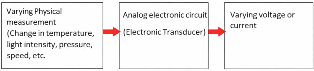
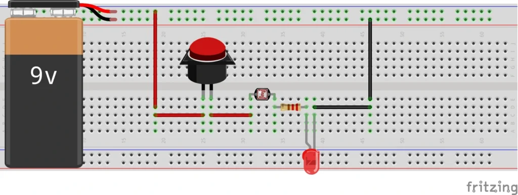
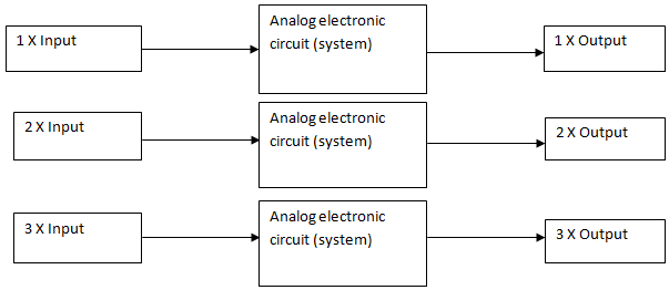
Figure 1 above shows a block diagram of a physical change measurement being converted to voltage or current using an analog electronic circuit. Figure 2 shows an electronic circuit that can convert a varying physical measurement to varying current.
The circuit contains a light dependent resistor (LDR). A light dependent resistor is a resistor whose resistance varies with respect to the amount of light shining on it. As the light intensity on the LDR increases, its resistance decreases, and as the light intensity decreases its resistance increases. This constitutes a varying physical system.
With the help of an analog electronic circuit, we can measure this varying light intensity in the form of current that flows through a light emitting diode (LED).
When you turn on the switch, and gradually cover the LDR, the light intensity on the LDR decreases. The resistance of the LDR increases up to 10,000,000Ω = 10MΩ, when this happens, current flow through the LED will gradually reduce in intensity, because the resistance along its path of flow has drastically reduced as a result of the increased resistance of the LDR.
But, when you gradually remove your hand from the LDR and have the LDR exposed in such a way that a reasonable amount of light shines on it, the resistance of the LDR will decrease tending to 0Ω. When this happens, the current flow through the LED will see little to no resistance on the LDR, the fixed resistance it will see is the 220Ω resistance of the current limiting resistor, which is there to protect the LED from getting fried from high current. So, as your hand is gradually removed from the LDR, the LED gradually brightens up.
If this action of covering and uncovering of the LDR is gradually repeated, the LED will be gradually going ON and OFF.
With this analog electronic circuit, we are actually monitoring and tracking light intensity. If we connect an ammeter in series with the LDR, we can measure the intensity of light on the LDR by multiplying the measured current by a factor. To learn how to use a multimeter like a professional, check out our Practical electronics circuit design course for the absolute beginner
If we connect a voltmeter across the LDR, we can measure the voltage drop on the LDR. By multiplying this voltage value by a factor, we can measure the varying intensity of light on the LDR. The bottom line is this: we are tracking a varying physical system (change in light intensity) with varying voltage and current.
This electronic circuit that takes in a varying input and in turn produces a varying output is called an analog electronic circuit. But if the system takes in a varying input and produces a steady output, like ON or OFF without a lower value ON (like a LED dimming as in the case above), such an electronic circuit is called a digital electronic circuit.
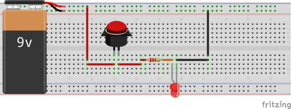
Figure 3 above is a simple LED circuit to explain a digital system. When the switch is pressed, the LED comes ON with a steady brightness and when the switch is turned OFF, the LED goes off. In the event of pressing the switch, the LED is either ON or OFF, there is nothing like lower brightness or higher brightness. The LED having only an OFF or ON state is a typical digital electronic circuit implementation. In digital electronics, no matter the variation of the measured system, the output or result is either 0 or 1, HIGH or LOW, ON or OFF, 5 volts or 0 volts, 3.3 volts or 0 volts.
Figure 3 above is similar to figure 2; the only difference is the removal of the LDR from figure 3.
In the analog system, the varying brightness of the LED tells us that the system is analog, while in the digital system, the LED only takes two distinct stats, either ON or OFF.
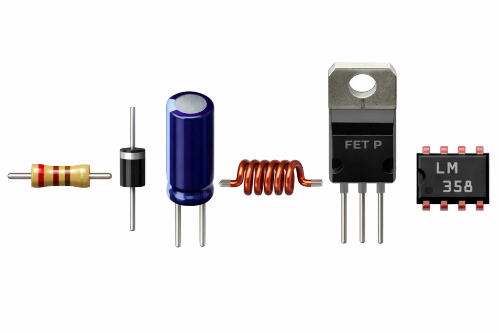
Some Components Used to Design Analog Circuits
The design of analog electronic circuit requires bunch of discrete components and some integrated circuits (IC) listed below:
- Resistors
- Diodes
- Capacitors
- Inductors
- Transistors
- Operational amplifiers (Op Amp)
We discussed most of these components in detail in our practical electronics circuit design course, a course that was created to take you from knowing nothing about electronics circuit design, to mastering the fundamentals of electronics circuit design from scratch.
On the other hand, digital electronic circuits are built from logic gate integrated circuits. It’s quite disappointing that some people do not know that the various logic gates taught in classrooms are integrated circuits (IC). The AND gate has an integrated circuit that carries out the function it is known to perform.
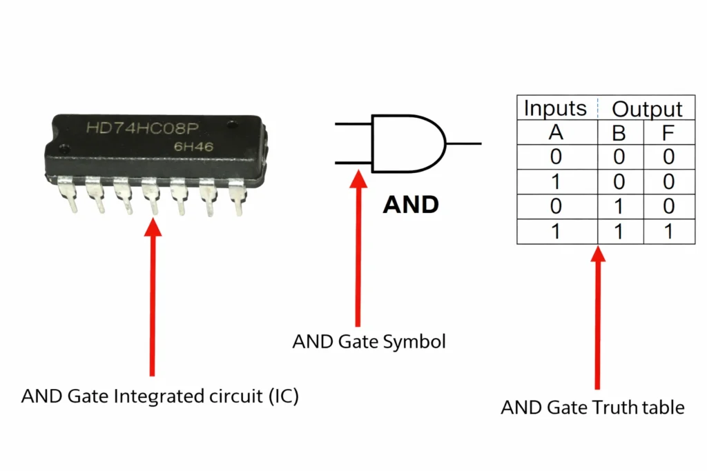
With the logic gates we obtain combinational logic gates, and with the combinational logic gates we obtain the sequential logic gates. All of these we shall cover in the digital electronics course we will create in the future.
Linearity in Analog Electronics
Most people refer to analog electronic circuits as “Linear” electronic circuits. Now, here is the reason, if you look back to the analog electronic circuit we have in figure 2, you will observe that as the intensity of light on the LDR increases, the current flowing into the LED increases. This is a proportionate relationship, whereby increase in input brings about increase in output. Such a relationship is called a “Linear Relationship.”
Analog systems are used to depict linear systems. Hence, we can call analog systems linear systems, and analog electronic circuits can as well be termed linear electronic circuits.
The figure above shows a linear relationship between the input and output. When an analog system acts on the input, the output or result obtained is linearly proportionate with the input.
Summary
- Analog electronic circuit is the same as linear electronic circuit
- Analog electronic circuit is an electronic circuit that handles varying signals (physical measurements) as input, and brings out proportionate varying signals (voltage and current) as output.
- Analog electronic circuits are designed with discrete electronic components and operational amplifiers.
- Digital electronic circuits are circuits that operate on the principles of binary digits (0 or 1).
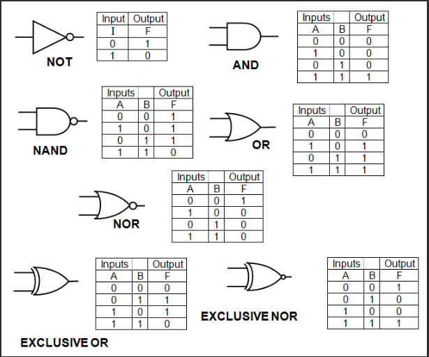
- Logic gates are the building blocks of digital electronic circuits, followed by combinational logic gates and sequential logic gates.
- Logic gates can be implemented with their corresponding logic gate integrated circuits.