LED Chaser Circuit project
Coding with Arduino, TUTORIALS

Arduino LED Chaser Circuit Project for Beginners | 6 LED Patterns + Push Button Control

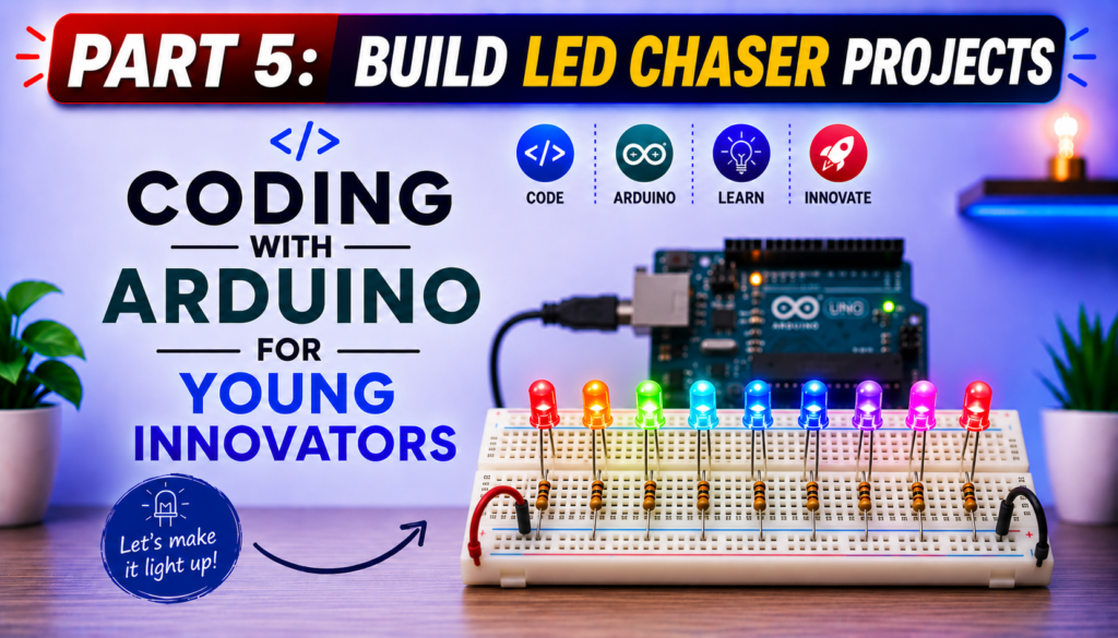
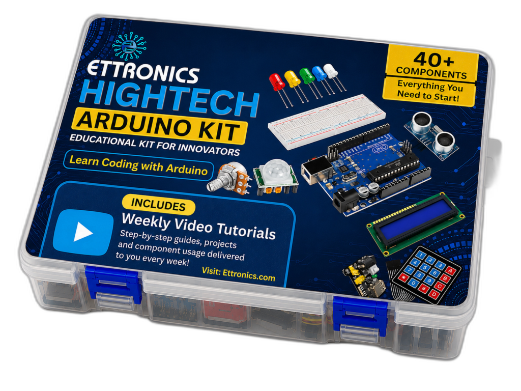
Arduino LED Chaser Circuit Project for Beginners (6 LED Patterns + Bonus Push Button Project) Imagine turning a row of ordinary LEDs into exciting moving light animations with just a few lines of Arduino code. That’s exactly what you’ll build in this tutorial. In this beginner-friendly Arduino project, you’ll learn how to create a fascinating LED Chaser Circuit using an Arduino UNO R3, 10 LEDs, and a breadboard. Instead of simply turning one LED on and off, you’ll control multiple LEDs to create animated lighting effects that move, bounce, and flow across the circuit. By the end of this tutorial, you’ll not only understand how to control multiple LEDs individually but also how to write cleaner Arduino programs using loops, arrays, and functions. We’ll even build a bonus project that uses a push button to switch between six different LED chaser patterns, making the project interactive and much more fun. Whether you’re a child learning Arduino for the first time, a parent teaching STEM at home, a teacher introducing electronics in the classroom, or simply a beginner interested in coding, this project provides an enjoyable way to practice both programming and circuit design. In this guide, you’ll learn: If you’ve already completed our LED Blinking Project, this lesson is the perfect next step because it introduces more advanced programming concepts while still being easy enough for complete beginners to follow. Let’s start by understanding what an LED chaser circuit is and why it’s one of the most popular beginner Arduino projects. What You Will Build By the end of this project, you will have built an exciting Arduino-powered LED chaser capable of displaying six different lighting animations. Each pattern demonstrates a different way of controlling multiple LEDs using code, helping you understand how timing, loops, and digital outputs work together. The bonus feature of this project is a push button that allows you to switch between the different LED patterns without changing or uploading new code. Simply press the button to cycle through the animations and watch your circuit respond instantly. This project is an excellent introduction to creating interactive electronic systems and lays the foundation for more advanced Arduino projects involving displays, motors, sensors, and robotics. Skills You Will Learn After completing this tutorial, you will be able to: What Is an LED Chaser Circuit? An LED chaser circuit is an electronic circuit in which multiple LEDs turn on and off in a programmed sequence, creating the illusion of moving or flowing light. Instead of illuminating all the LEDs at the same time, the lights are activated one after another according to a specific pattern. The movement of the lights is controlled entirely by software running on the Arduino. By changing just a few lines of code, you can create countless lighting effects, from a simple left-to-right chase to more advanced animations that move in opposite directions, bounce back and forth, or light up randomly. An LED chaser is one of the most popular beginner electronics projects because it combines two essential skills: Unlike the basic LED Blink project, where only one LED is controlled, this project introduces multiple digital outputs working together. As a result, you’ll gain a better understanding of how microcontrollers can coordinate several devices simultaneously. How Does an LED Chaser Work? The Arduino UNO controls each LED through one of its digital output pins. When a digital pin is set HIGH, the corresponding LED receives voltage and lights up. When the pin is set LOW, the LED turns off. By rapidly switching different pins on and off in a carefully timed sequence, the Arduino creates the appearance of a moving light. Although only one or a few LEDs may be on at any given moment, the switching happens so quickly that our eyes perceive a smooth animation. The speed of the animation is controlled by the delay() function. Short delays produce fast-moving effects, while longer delays create slower, more noticeable light movements. As you progress through this tutorial, you’ll discover that even simple programming structures, such as for loops, arrays, and functions, can produce surprisingly impressive visual effects. Real-World Applications of LED Chaser Circuits Although this project is designed for learning, the same principles are used in many real-world electronic systems. Understanding how an LED chaser works provides a foundation for designing more advanced control systems in the future. Some common applications include: Many of these systems use the same idea you’re learning here: turning outputs on and off in a carefully timed sequence to create meaningful visual effects. Why This Project Is Great for Beginners The LED Chaser Project builds directly on the skills learned in the LED Blink Project while introducing several important programming concepts without becoming overwhelming. By completing this project, you’ll practice: These are foundational skills you’ll use repeatedly as you move on to more advanced Arduino projects involving LCDs, sensors, motors, robotics, and the Internet of Things (IoT). What You Will Learn in This Tutorial By the end of this guide, you will be able to: These skills will not only help you complete this project but will also prepare you for more advanced Arduino programming challenges in future lessons. Components Required for the Arduino LED Chaser Project Before we start building the circuit, let’s gather all the components you’ll need. One of the best things about this project is that it uses inexpensive, readily available parts, making it perfect for beginners, students, and STEM classrooms. The components used for this project part of the components in out ettronics Coding with Arduino Kit. Unlike the LED Blink Project, which uses just one LED, this tutorial uses 10 LEDs to create exciting lighting animations. Each LED is connected to a separate Arduino digital pin, allowing the microcontroller to control them individually and produce different chasing patterns. The table below lists all the materials required and explains why each one is important. Component Quantity Purpose Arduino UNO R3 1 The microcontroller that controls the LEDs and executes the program. Breadboard 1

Coding with Arduino for Beginners
Coding with Arduino, TUTORIALS

Arduino LED Blink Tutorial for Beginners | Coding with Arduino for Young Innovators

Arduino LED Blink Tutorial for Beginners (Step-by-Step Guide) Learning to program an Arduino is one of the most exciting ways to begin your journey into electronics, robotics, and embedded systems. If you’ve never written a line of code before, don’t worry, this tutorial is designed specifically for beginners, children, parents, teachers, and aspiring innovators who want to learn through practical, hands-on projects. In this lesson, you’ll build one of the most famous beginner projects in electronics: the Arduino LED Blink Project. Although it may seem simple, this project introduces nearly every fundamental concept you’ll use in future Arduino programming, including writing code, uploading programs to a microcontroller, controlling digital outputs, and understanding how a program executes continuously. Whether your goal is to build robots, smart home systems, IoT devices, automation projects, or simply learn programming from scratch, the LED Blink project is the perfect place to start. This tutorial is part of our Coding with Arduino for Young Innovators series, where every lesson builds practical skills through easy-to-understand explanations and exciting projects. Why Every Beginner Starts with the LED Blink Project If you’ve ever searched online for beginner Arduino projects, you’ve probably noticed that almost everyone starts with blinking an LED. That’s not because it’s the easiest project, it’s because it teaches almost every basic programming concept you’ll need later. By completing this project, you’ll learn how to: These skills become the foundation for more advanced projects involving sensors, LCD displays, motors, Bluetooth, Wi-Fi, IoT, and robotics. What You Will Learn By the end of this tutorial, you will understand: If this is your very first Arduino project, you’re in the right place. What Is Arduino? Arduino is an open-source electronics platform that combines both hardware and software to make programming electronic devices simple and accessible. Instead of designing complex electronic circuits from scratch, Arduino provides a programmable microcontroller board that can interact with the outside world. By writing a few lines of code, you can control LEDs, motors, sensors, displays, relays, and many other electronic components. The Arduino platform has become one of the most popular learning tools for: One reason Arduino is so popular is its simplicity. Even someone with no programming experience can build useful projects within a few hours. What Is the Arduino UNO R3? For this lesson, we’re using the Arduino UNO R3, one of the most popular development boards in the world. The Arduino UNO R3 is powered by the ATmega328P microcontroller, which acts as the “brain” of the board. It executes the programs you upload and controls the connected electronic components. Some key features of the Arduino UNO R3 include: These features make the Arduino UNO R3 ideal for learning electronics and programming. As you progress through this course, you’ll use these pins to connect sensors, buzzers, LCDs, ultrasonic modules, Bluetooth devices, Wi-Fi modules, and much more. What Is an LED? An LED (Light Emitting Diode) is a small electronic component that emits light when electrical current flows through it. Unlike ordinary light bulbs, LEDs consume very little power while producing bright light, making them ideal for electronic projects. LEDs come in many colors, including: An LED has two legs: Long Leg (Anode) The longer leg is the positive terminal and should be connected toward the positive voltage through a current-limiting resistor. Short Leg (Cathode) The shorter leg is the negative terminal and is connected to Ground (GND). If you connect the LED backward, it will not light up because LEDs only allow current to flow in one direction. Why Do We Need a Resistor? One of the biggest mistakes beginners make is connecting an LED directly to an Arduino pin. This can allow too much current to flow through the LED, potentially damaging both the LED and the Arduino’s output pin. To prevent this, we use a 220 Ω to 330 Ω resistor in series with the LED. You can check out our resistor calculator software. The resistor limits the current flowing through the LED, ensuring safe operation while maintaining sufficient brightness. Think of the resistor as a traffic controller, it slows the flow of electrical current to a safe level. Components Required To complete this project, you’ll need the following components: Component Quantity Arduino UNO R3 1 Breadboard 1 LED 1 220 Ω or 330 Ω Resistor 1 Jumper Wires 2–3 USB Type A to Type B Cable 1 Computer with Arduino IDE 1 These components are inexpensive and form the basis of countless Arduino projects. Installing the Arduino IDE Before you can program your Arduino UNO R3, you need to install the Arduino Integrated Development Environment (IDE). The Arduino IDE is the software used to write, compile, and upload code to your Arduino board. The Arduino IDE is beginner-friendly and works on Windows, macOS, and Linux. It provides a simple code editor, tools for selecting your board and communication port, and a built-in serial monitor for debugging. Step 1: Download the Arduino IDE Visit the official Arduino website and download the latest version of the Arduino IDE that matches your operating system. Choose the installer for: Once the download is complete, run the installer and follow the on-screen instructions. Step 2: Install the Software After downloading: The installation process usually takes only a few minutes. Connecting the Arduino UNO R3 to Your Computer After installing the Arduino IDE, it’s time to connect your Arduino board. Use a USB Type-A to Type-B cable (often called a printer USB cable). Plug: If everything is connected correctly: Configuring the Arduino IDE Before uploading your program, you must tell the Arduino IDE which board you’re using and which communication port it is connected to. Selecting the Board In the Arduino IDE: This ensures the IDE compiles your code for the correct microcontroller. Selecting the COM Port Next: If you’re unsure which port is correct: Selecting the wrong port will prevent the IDE from uploading your code. Building the LED Blink Circuit Now comes the fun part, building your first electronic circuit. Although the

555 timer calculator
TOOLS

555 Timer Astable Calculator and 555 Timer Monostable Calculator – Complete Tool

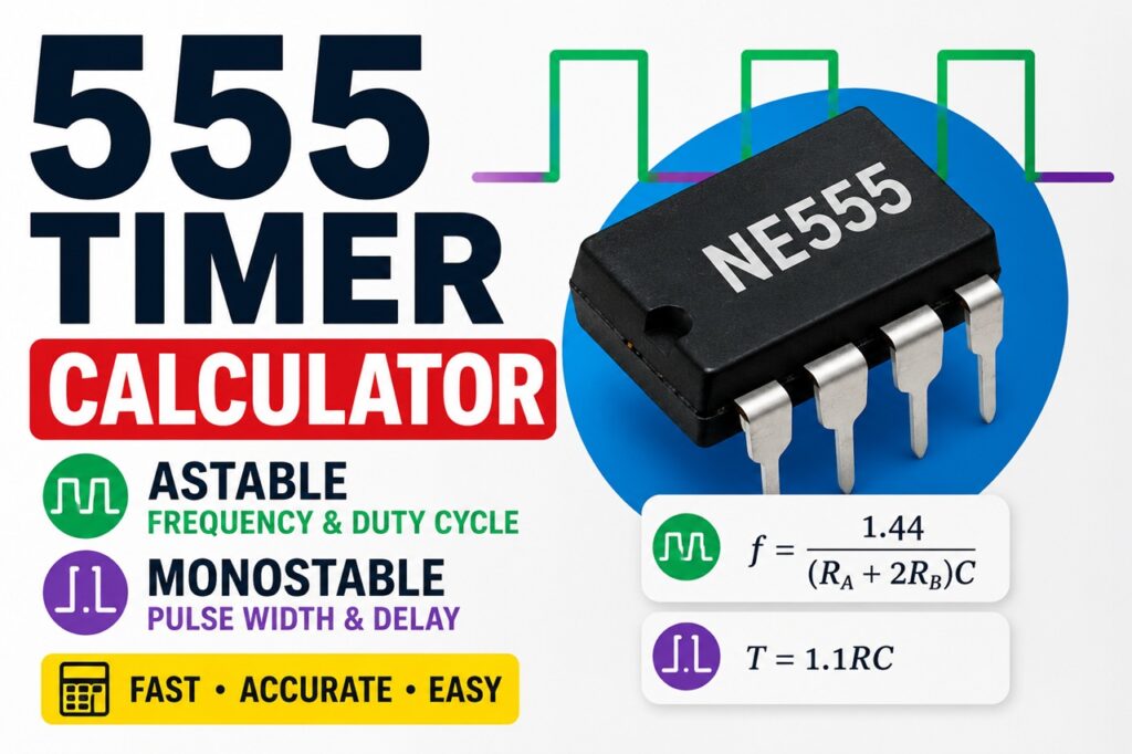
If you’re looking for a reliable 555 timer astable calculator or 555 timer monostable calculator, you’ve come to the right place. The 555 timer IC is one of the most popular integrated circuits ever created, and it remains a cornerstone of electronics design for students, hobbyists, technicians, and professional engineers. From blinking LEDs and alarm circuits to pulse generators and delay timers, the 555 timer offers a simple and cost-effective solution for a wide range of applications. However, manually calculating frequency, duty cycle, pulse width, and timing component values can be tedious and prone to error. That’s where the Ettronics 555 Timer Calculator comes in. It automatically calculates all the important parameters for both astable and monostable configurations, helping you design accurate circuits faster. What Is a 555 Timer? The 555 timer is an eight-pin integrated circuit designed for generating precise timing signals. It can operate in different modes, but the two most commonly used are: In astable mode, the circuit continuously oscillates between HIGH and LOW states. In monostable mode, the circuit generates a single output pulse whenever it receives a trigger signal. Because of its simplicity, low cost, and reliability, the 555 timer continues to be used in countless electronic circuits worldwide. Common applications include: What Is a 555 Timer Astable Calculator? A 555 timer astable calculator is a tool used to determine the operating characteristics of a 555 timer configured as a free-running oscillator. In astable mode, the output continuously alternates between HIGH and LOW without requiring an external trigger. The calculator automatically computes: based on the selected resistor and capacitor values. How the Astable Mode Works In an astable configuration, the timing capacitor repeatedly charges and discharges through the resistor network. As the capacitor voltage rises and falls between the internal threshold levels of the 555 timer, the output switches state, producing a continuous square-wave signal. This behavior makes astable mode ideal for: 555 Timer Astable Formula The oscillation frequency depends on the values of: Frequency Formula Where: Period Formula Where: High Time Formula Low Time Formula Duty Cycle Formula The Ettronics 555 Timer Astable Calculator automatically performs these calculations and presents the results in user-friendly engineering units. Example Astable Calculation Suppose you select: The calculator instantly determines: without requiring manual calculations. Practical Uses of Astable Mode LED Blinkers Generate flashing LEDs for indicators and warning systems. Oscillators Create continuous square-wave signals for testing and timing. Clock Generators Provide timing pulses for counters and digital circuits. Alarm Circuits Generate repetitive signals for buzzers and sirens. Educational Demonstrations Help students understand capacitor charging and discharging behavior. What Is a 555 Timer Monostable Calculator? A 555 timer monostable calculator is used to calculate the pulse duration of a one-shot timer circuit. Unlike astable mode, a monostable circuit remains stable until triggered. When a trigger signal is applied: This makes monostable mode ideal for generating accurate delays. How the Monostable Mode Works In a monostable configuration: Because only one pulse is generated for each trigger, this configuration is often called a one-shot timer. 555 Timer Monostable Formula The pulse duration depends on the timing resistor and capacitor. Pulse Width Formula Where: The Ettronics 555 Timer Monostable Calculator instantly computes the pulse duration based on the selected component values. Example Monostable Calculation Suppose you choose: The pulse width becomes: Instead of performing these calculations manually, the calculator provides the result instantly. Astable vs Monostable Mode Feature Astable Mode Monostable Mode Trigger Required No Yes Output Continuous Oscillation Single Pulse Frequency Generation Yes No Delay Generation Limited Excellent LED Flashing Excellent Limited Oscillator Function Excellent No Pulse Generation Continuous One-Shot Why Use the Ettronics 555 Timer Calculator? The Ettronics Electronics Calculator platform provides much more than basic calculations. Real-Time Calculations Results update automatically as values are entered. Formula Display View the actual equations used for each calculation. Engineering Unit Conversion Convert values between: Circuit Schematics Visual diagrams help users understand circuit connections. Mobile-Friendly Interface Designed to work perfectly on phones, tablets, and desktop computers. Educational Explanations Learn how the calculations are derived while designing your circuit. Common 555 Timer Design Mistakes Choosing Extremely Large Capacitors Large electrolytic capacitors can introduce leakage errors. Using Very Small Resistor Values Low resistance values may overload the discharge transistor. Ignoring Power Supply Decoupling A 100 nF capacitor between VCC and GND helps improve stability. Leaving the Reset Pin Floating Pin 4 should typically be connected to VCC. Ignoring Duty Cycle Limitations Standard astable circuits cannot naturally produce a perfect 50% duty cycle without modifications. Understanding Duty Cycle Duty cycle describes the percentage of time the output remains HIGH during one complete cycle. The formula is: Where: This parameter is particularly important in oscillator and pulse generation applications. Who Should Use a 555 Timer Calculator? The calculator is ideal for: Whether you are designing a simple LED flasher or a complex timing circuit, accurate calculations help ensure reliable performance. Final Thoughts A dependable 555 timer astable calculator and 555 timer monostable calculator can significantly simplify the design process. Instead of manually solving equations, converting units, and checking calculations, the Ettronics 555 Timer Calculator provides instant results for frequency, duty cycle, pulse width, high time, low time, and timing component selection. By combining real-time calculations, engineering unit conversion, mathematical formulas, educational explanations, and circuit schematics, the calculator serves as both a practical design tool and a learning resource for anyone interested in electronics. Whether your goal is to build an oscillator, delay timer, pulse generator, or timing circuit, the Ettronics 555 Timer Calculator provides the accuracy and convenience needed to bring your design to life. See more Calculators:

battery runtime calculator
TOOLS

Battery Runtime Calculator – Calculate Battery Life, Backup Time, Ah, Wh & kWh

Have you ever wondered how long your battery will last before it needs recharging? Whether you are designing a solar power system, sizing a battery bank for an inverter, building an electronics project, or planning backup power for a UPS system, knowing the expected battery runtime is essential. Our Battery Runtime Calculator helps you estimate battery life, backup time, battery energy, and runtime in hours, minutes, and days. It supports various battery technologies, including LiFePO4, lithium-ion, AGM, gel, and lead-acid batteries. What Is a Battery Runtime Calculator? A Battery Runtime Calculator is a tool used to estimate how long a battery can power a load before it becomes discharged. The calculator considers factors such as: By combining these parameters, the calculator provides a realistic estimate of how long your battery system can operate. Why Battery Runtime Matters Battery runtime calculations are important in many applications: Solar Power Systems Solar installers use battery runtime calculations to determine how long batteries can power appliances during periods of low sunlight. Inverter Systems Home and office inverter systems rely on battery banks for backup power. Knowing the expected runtime helps prevent unexpected outages. UPS Systems Businesses use UPS batteries to provide emergency power during blackouts. Accurate runtime estimates help determine whether the UPS can support critical equipment long enough for safe shutdown. Electronics Projects Engineers, technicians, hobbyists, and students frequently calculate battery life for Arduino, ESP32, Raspberry Pi, IoT devices, and portable electronics. Understanding Battery Capacity (Ah) Battery capacity is usually expressed in Ampere-hours (Ah). For example: A higher Ah rating generally means longer runtime, provided the load remains the same. Example A 100Ah battery can theoretically supply: However, real-world factors such as efficiency losses and depth of discharge affect actual runtime. Understanding Battery Voltage Battery voltage determines how much energy is stored. Common battery voltages include: The same Ah rating can provide very different energy storage depending on voltage. For example: The 24V battery stores twice as much energy. Battery Energy: Wh and kWh Battery energy is usually measured in: The formula is: Energy (Wh) = Voltage × Capacity (Ah) Example 12V × 100Ah = 1200Wh 1200Wh ÷ 1000 = 1.2kWh This means the battery stores approximately 1.2 kilowatt-hours of energy. How Battery Runtime Is Calculated The calculator uses the battery’s stored energy and compares it with the load power. Factors considered include: This provides a more realistic estimate than simple battery calculations. Battery Types Supported LiFePO4 Batteries LiFePO4 batteries offer: Recommended DOD: approximately 90% Lithium-Ion Batteries Lithium-ion batteries provide: Recommended DOD: approximately 80% AGM (Absorbent Glass Mat) Batteries AGM batteries are: Recommended DOD: approximately 50% Gel Batteries Gel batteries offer: Recommended DOD: approximately 50% Lead-Acid Batteries Traditional lead-acid batteries remain popular due to affordability and availability. Recommended DOD: approximately 50% What Is Depth of Discharge (DOD)? Depth of discharge indicates how much of the battery capacity is safely usable. For example: A 100Ah battery with 50% DOD provides approximately 50Ah of usable capacity. Using batteries beyond their recommended DOD can shorten lifespan significantly. What Is Inverter Efficiency? Inverter efficiency measures how effectively an inverter converts DC battery power into AC power. Typical values include: Higher efficiency means more battery energy reaches your appliances. Battery Runtime Example Suppose you have: The battery will provide several hours of backup power depending on the overall system efficiency and operating conditions. Our calculator performs these calculations automatically. Factors That Affect Battery Life Several factors influence actual runtime: Temperature Extreme temperatures reduce battery performance and lifespan. Battery Age Older batteries typically store less energy. Load Variations Appliances may consume more power during startup. Efficiency Losses Losses occur in: Battery Health Damaged or poorly maintained batteries often provide reduced runtime. Tips for Maximizing Battery Runtime Frequently Asked Questions How long will a 100Ah battery last? The answer depends on: A 100Ah battery powering a small load may last many hours, while a large load will reduce runtime significantly. What is the difference between battery life and battery runtime? Battery runtime refers to how long the battery can power a load during a single discharge cycle. Battery life refers to the overall lifespan of the battery over many charge-discharge cycles. Why is my actual runtime shorter than the calculated value? Possible reasons include: Are LiFePO4 batteries better for backup power? LiFePO4 batteries generally provide: They are often preferred for solar and inverter applications. Conclusion A reliable Battery Runtime Calculator helps you estimate backup time, battery life, battery energy, and power availability before installing or purchasing a battery system. Whether you are working with solar batteries, UPS systems, inverter batteries, LiFePO4 batteries, AGM batteries, gel batteries, or traditional lead-acid batteries, understanding runtime helps you make better engineering and energy-management decisions. Use the Ettronics Battery Runtime Calculator above to instantly estimate battery runtime, battery energy, and backup duration for your next project or power system. If you are into solar installations, you may want to check out our Solar System Sizing Calculator, it is the professional tool you need to make informed decisions when sizing solar panels, batteries, inverters, charge controllers, for your solar system installations.

Solar system calculator
TOOLS

Solar Panel Calculator– Calculate Solar Panels, Batteries, Inverter Size & ROI Accurately

If you’re planning to install a solar power system, one of the biggest questions you’ll face is: How many solar panels do I need? Closely followed by: The good news is that you don’t have to guess. Our Solar System Calculator helps you accurately estimate solar panel size, battery bank capacity, inverter size, charge controller rating, generator size, daily energy production, ROI, and payback period in just a few minutes. Whether you are building a small backup system for your home or designing a large off-grid solar installation, this calculator provides practical estimates that can help you plan your project with confidence. What Is a Solar System Calculator? A solar system calculator is a tool that estimates the major components required for a solar power system based on your energy consumption. Instead of manually performing multiple calculations, the calculator automatically determines: This makes it useful for homeowners, businesses, solar installers, engineers, students, and renewable energy consultants. Why Proper Solar System Sizing Is Important One of the most common mistakes people make is purchasing solar components without calculating their actual energy requirements. An undersized system may result in: An oversized system may result in: Proper sizing helps ensure that every component works efficiently and safely. How a Solar Power System Works A typical solar energy system consists of several major components: Solar Panels Solar panels convert sunlight into electrical energy. The amount of electricity generated depends on: Charge Controller The charge controller regulates power flowing from the solar panels to the batteries. Its job is to: Battery Bank The battery bank stores energy for use when sunlight is unavailable. This allows the system to operate: Inverter The inverter converts battery DC power into AC power used by household appliances. Common inverter sizes include: Generator (Optional) Many backup and hybrid systems include a generator for emergency charging during extended periods of poor weather. How to Calculate Daily Energy Consumption Before sizing a solar system, you need to know your daily energy usage. The formula is: Daily Energy (Wh) = Load Power (W) × Hours of Use Example Suppose you have: Daily Energy = 1000 × 5 = 5000Wh = 5kWh per day This value forms the foundation of the entire solar design process. How Solar Panel Size Is Calculated The calculator estimates the required solar array using your daily energy requirement and local sunlight conditions. Factors considered include: Example Daily Energy Requirement: 5kWh Peak Sun Hours: 5 hours Required Solar Array: Approximately 1.5kW to 1.7kW Using 550W solar panels: Required Panels: 3 Panels How Battery Bank Size Is Calculated Battery capacity depends on: Why Days of Autonomy Matter Days of autonomy represent the number of days the battery bank can power the system without solar charging. Typical values: Application Days of Autonomy Backup Systems 1 Day Residential Off-Grid 2 Days Remote Locations 3 Days or More Increasing autonomy improves reliability but increases battery cost. How Many Batteries Do I Need? The answer depends on: For example: Required Battery Bank: 24V 400Ah Available Batteries: 12V 200Ah Possible Configuration: 2 Batteries in Series × 2 Parallel Total Batteries: 4 The calculator automatically determines battery quantity and configuration. How Inverter Size Is Determined The inverter must be large enough to handle: A safety margin is usually added to the calculated load. For example: Load: 1000W Recommended Inverter: 1500W Pure Sine Wave This allows the inverter to handle surge currents safely. What Is Peak Sun Hours? Peak Sun Hours (PSH) represent the equivalent number of hours per day that sunlight reaches maximum intensity. Examples: Location Peak Sun Hours Lagos 5.0 Abuja 5.5 Kano 6.0 Port Harcourt 4.5 The calculator includes sunlight database options and manual input for flexibility. Solar Battery Calculator Features The built-in battery calculator supports: Lead Acid Batteries Advantages: Disadvantages: AGM (Absorbent Glass Mat) Batteries Advantages: Gel Batteries Advantages: Lithium LiFePO4 Batteries Advantages: For most modern installations, LiFePO4 batteries offer the best long-term value. Solar Inverter Calculator Features The inverter calculator helps determine: It supports: Battery Bank Calculator Features The battery bank calculator estimates: This helps users avoid undersized battery banks. Off-Grid Solar Calculator For off-grid systems, the calculator becomes even more valuable because it considers: Off-grid systems must be carefully sized because there is no utility grid available as a backup. ROI Calculator for Solar Systems The calculator can also estimate financial performance. By entering: You can estimate: This helps determine whether a solar project is financially worthwhile. AI-Powered Solar Recommendations One of the unique features of the Ettronics Solar System Calculator is the optional AI recommendation engine. The AI can provide: These recommendations help users better understand their results. Who Should Use This Solar Calculator? This tool is suitable for: Homeowners Planning backup or off-grid systems. Solar Installers Performing quick client estimates. Renewable Energy Consultants Generating preliminary system designs. Students Learning solar system design principles. Electrical Engineers Conducting preliminary feasibility assessments. Businesses Evaluating solar investment opportunities. Common Solar Sizing Mistakes Avoid these common mistakes: Underestimating Daily Energy Use Always calculate actual appliance usage. Ignoring Inverter Losses Inverters are not 100% efficient. Choosing Too Few Batteries Insufficient battery storage can reduce system reliability. Using Unrealistic Sunlight Values Use local peak sun hours whenever possible. Ignoring Future Expansion Leave room for future load growth. You can check out our Battery Runtime Calculator. Frequently Asked Questions How accurate is this solar system calculator? The calculator provides reliable preliminary estimates based on accepted solar sizing principles. Final installation designs should be verified by a qualified solar professional. Can I use this calculator for commercial projects? Yes. The calculator can be used for residential and commercial solar planning. Does the calculator work for lithium batteries? Yes. The battery module supports lithium battery calculations. What inverter size should I choose? Always select an inverter with sufficient margin above your expected load. Can this calculator determine wire size? The calculator can provide preliminary wire sizing guidance, but final cable selection must consider cable length, voltage drop, installation method, ambient temperature, and local electrical codes. Conclusion A properly sized

Voltage divider calculator
TOOLS

Voltage Divider Calculator – Calculate Output Voltage, Resistor Values & Divider Ratio

Voltage Divider Calculator helps you quickly determine the output voltage produced by two resistors connected in series. Instead of performing manual calculations, this tool can calculate the input voltage (Vin), output voltage (Vout), or resistor values (R1 and R2) required to achieve a desired voltage. Use the calculator below to instantly solve voltage divider problems and obtain accurate results. What Is a Voltage Divider? A voltage divider is a simple electronic circuit that uses two resistors connected in series to produce a lower voltage from a higher input voltage. The output voltage is taken from the junction between the two resistors. Voltage dividers are commonly used when a circuit requires a voltage level that is lower than the available supply voltage. For example: Voltage Divider Formula The voltage divider formula is: Vout=Vin×R2R1+R2V_{out}=V_{in}\times\frac{R_2}{R_1+R_2}​​ Where: The formula shows that the output voltage depends on the ratio between the two resistor values. How to Use the Voltage Divider Calculator Using the calculator is straightforward: Step 1 Select what you want to calculate: Step 2 Enter the known values. Step 3 Select the appropriate units. Step 4 Click Calculate. Step 5 Review the results and recommendations. Example Voltage Divider Calculation Suppose: Applying the formula: Vout=12×500010000+5000V_{out}=12\times\frac{5000}{10000+5000}​ Result: Vout = 4V This means a 12V supply can be reduced to approximately 4V using these resistor values. Common Applications of Voltage Dividers Voltage dividers are used in countless electronic circuits. Sensor Interfacing Many sensors output voltages that must be scaled before entering a microcontroller. Examples: ADC Input Scaling Microcontrollers such as: often have voltage limitations on their analog inputs. Voltage dividers help reduce higher voltages to safe levels. Reference Voltage Generation Voltage dividers can create stable reference voltages for: Battery Monitoring Battery voltages frequently exceed the safe input range of ADC pins. Voltage dividers are commonly used to monitor battery levels safely. Advantages of Voltage Dividers Limitations of Voltage Dividers Although useful, voltage dividers have limitations. Load Effects Connecting a load to the output changes the effective resistance and may alter the output voltage. Not Suitable for High Current Loads Voltage dividers are intended for signal-level applications rather than powering devices. Reduced Accuracy Resistor tolerances affect output voltage accuracy. Using 1% resistors generally produces better results than 5% resistors. Common Voltage Divider Mistakes Using Incorrect Resistor Values Always verify resistor values before assembly. Ignoring Resistor Tolerance Resistors are not perfect and can vary from their nominal value. Forgetting Load Resistance The connected circuit can significantly affect the output voltage. Using a Voltage Divider as a Power Supply Voltage dividers are not designed to power heavy loads. Practical Design Tips Frequently Asked Questions What does a voltage divider do? A voltage divider reduces an input voltage to a lower output voltage using two resistors connected in series. Can a voltage divider increase voltage? No. A voltage divider can only reduce voltage. What happens if R1 equals R2? When R1 and R2 have the same value, the output voltage becomes half of the input voltage. Why is my measured output voltage different from the calculated value? Possible reasons include: Can I use a voltage divider with an Arduino or ESP32? Yes. Voltage dividers are commonly used to scale voltages for Arduino and ESP32 analog input pins. Final Thoughts A voltage divider is one of the most important circuits in electronics. Understanding how it works can help you design sensor interfaces, scale voltages for microcontrollers, generate reference voltages, and troubleshoot electronic circuits more effectively. Use the Voltage Divider Calculator above whenever you need to quickly determine Vin, Vout, R1, or R2 without performing manual calculations. Whether you are an electronics student, hobbyist, maker, technician, or engineer, voltage dividers are among the most frequently used circuits in electronic design. For more electronics tools, explore our growing collection of calculators and tutorials on Ettronics.

LED current limiting resistor calculator
TOOLS

LED Current Limiting Resistor Calculator

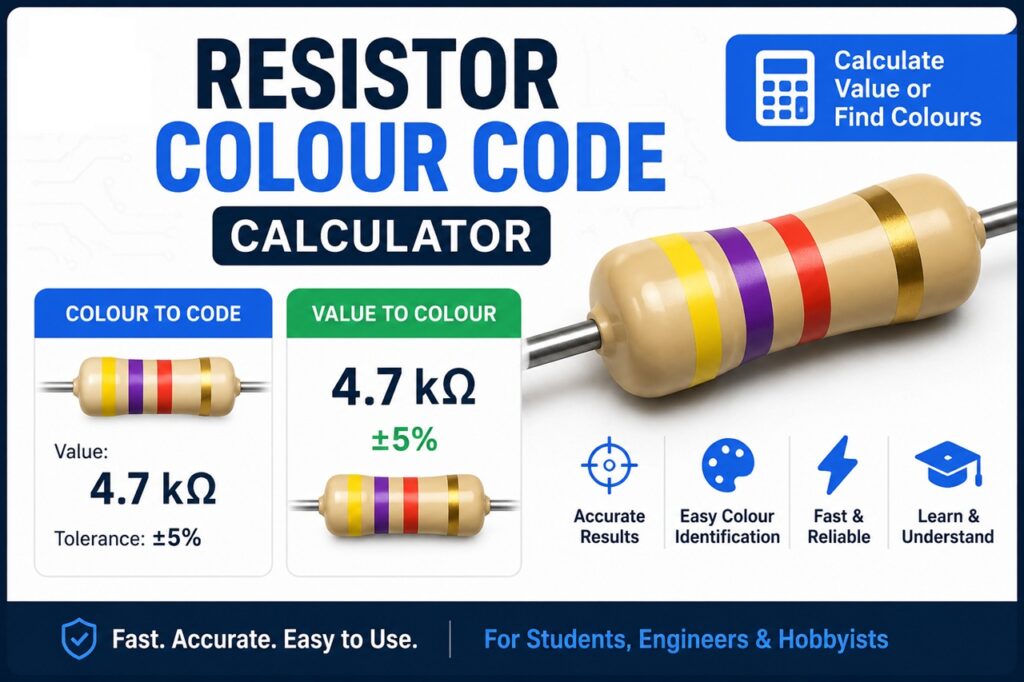
If you have ever connected an LED directly to a battery or power supply and watched it burn out instantly, then you already understand why a current limiting resistor is important. A current limiting resistor helps protect an LED from drawing too much current. Without it, the LED may overheat, fail permanently, or have a very short lifespan. To make things easier, we created this free LED Current Limiting Resistor Calculator to help you quickly determine the correct resistor value for your LED circuit. What Is an LED Current Limiting Resistor? An LED (Light Emitting Diode) current limiting resistor is a resistor connected in series with an LED to control the amount of current flowing through it. Unlike incandescent bulbs, LEDs are current-sensitive electronic components. Even a small increase in current can damage them. The resistor absorbs the excess voltage from the power supply and ensures the LED receives only the current it is designed to handle. Why LEDs Need a Current Limiting Resistor LEDs operate within a safe current range. For example: If you connect an LED directly to a voltage source without limiting the current, the LED may: Using the correct resistor prevents these problems. Formula for LED Current Limiting Resistor The formula used in this calculator is: \[ R=\frac{V_s-(V_{led}\times X)}{I_{led}} \] Where: Understanding Each Parameter 1. Supply Voltage (Vs) This is the voltage source powering the circuit. Examples: 2. LED Forward Voltage (Vled) This is the voltage drop across a single LED when operating normally. Different LED colours usually have different forward voltages. Typical values: LED Colour Typical Forward Voltage Red 1.8V – 2.2V Yellow 2.0V – 2.2V Green 2.0V – 3.2V Blue 3.0V – 3.5V White 3.0V – 3.5V 3. Number of LEDs in Series (X) This refers to how many LEDs are connected one after another in series. If you have: 4. LED Current (Iled) This is the operating current of the LED. Most standard LEDs operate at: Some high-power LEDs may use: Example Calculation Suppose you want to connect: Using the formula: \[ R=\frac{12-(2\times3)}{0.02} \] Result: \[ R=300\ \Omega \] So the required resistor value is: You can use the nearest standard resistor value. How to Choose the Nearest Standard Resistor Value Sometimes the exact resistor value calculated may not exist. In that case, choose the nearest higher standard resistor value. For example: Calculated Value Recommended Standard Value 287Ω 300Ω 315Ω 330Ω 470Ω 470Ω 980Ω 1kΩ Choosing a slightly higher resistor is safer than choosing a lower one. How to Calculate Resistor Power Rating The resistor also dissipates power as heat. Power is calculated using: P=I^2R Where: In most small LED circuits: For higher currents, you may need: Common Mistakes When Using LEDs 1. Connecting LEDs Directly to Power This is the most common beginner mistake. Always use a resistor unless the LED module already includes one. 2. Using the Wrong LED Voltage Different LED colours have different forward voltages. Always check the LED datasheet if possible. 3. Mixing LEDs with Different Characteristics When LEDs with different voltages are mixed in series, current distribution may become uneven. 4. Using Too Low Resistor Values Lower resistor values increase current and may damage the LED. Can You Use One Resistor for Multiple LEDs? Yes — if the LEDs are connected in series. However, for parallel LED connections, it is usually safer to use separate resistors for each LED branch. Series vs Parallel LED Connections LEDs in Series Advantages: Disadvantages: LEDs in Parallel Advantages: Disadvantages: Applications of LED Current Limiting Resistors These resistors are used in: Frequently Asked Questions (FAQ) What happens if the resistor value is too low? The LED may draw excessive current and burn out. What happens if the resistor value is too high? The LED will become dim because less current flows through it. Can I use a potentiometer instead? Yes, a potentiometer can vary LED brightness, but a fixed resistor is more stable for permanent circuits. Why does my LED still get hot? Possible reasons include: Can this calculator be used for high-power LEDs? Yes, but high-power LEDs often require proper current drivers and heatsinks. Final Thoughts Choosing the correct resistor for an LED is one of the most important basics in electronics. Using the proper current limiting resistor helps: Instead of calculating manually every time, you can use the LED Current Limiting Resistor Calculator above to get fast and accurate results for your projects. If you found this calculator useful, check out our other electronics calculators and DIY electronics tutorials on Ettronics.

How to test a transistor using a digital multimeter
Electronics Tutorial, TUTORIALS

How to Test a Transistor Using a Multimeter (Step-by-Step Beginner Guide)

Have you ever built a circuit, repaired an amplifier, or worked on an electronics project only to discover that it simply refuses to work? In many cases, one small component can be responsible: the transistor. Transistors are among the most commonly used components in electronics, and because they are used as switches and amplifiers in almost every modern circuit, a faulty transistor can stop an entire system from functioning correctly. The good news is that you do not need expensive equipment to test one. A standard digital multimeter can quickly help you determine whether a transistor is healthy or damaged. In this guide, you will learn: Let’s begin. What Is a Transistor? A transistor is a semiconductor device used to control electrical current. It mainly serves two functions: You can think of a transistor as an electronically controlled switch. A small current entering one terminal can control a larger current flowing through the other terminals. Most beginners will commonly encounter two major transistor types: Both types typically have three terminals: Testing either type with a multimeter is relatively similar, although the probe connections differ. Tools Needed Before you begin, gather the following: A digital multimeter with diode mode is highly recommended because it provides more reliable results than continuity mode. Safety Precautions Before Testing Before testing any transistor: Testing a transistor while it remains connected in a circuit may produce incorrect readings because nearby components can affect measurements. Identify the Transistor Pins First Before placing multimeter probes on a transistor, you need to identify its terminals: Different transistors may have different pin arrangements. For example: A TIP41 transistor may use: Pin Function 1 Base 2 Collector 3 Emitter Another transistor may use a different arrangement. The safest approach is checking the transistor datasheet before testing. Understanding Diode Mode on a Multimeter Most digital multimeters have a diode test mode. Diode mode measures the voltage drop across semiconductor junctions. Since a transistor contains two PN junctions internally, testing a transistor in diode mode effectively tests those junctions. For a healthy transistor, typical readings are: How to Test an NPN Transistor Using a Multimeter Watch video below. Follow these steps carefully. Step 1: Set Your Multimeter to Diode Mode Rotate the multimeter dial to diode test mode. Step 2: Connect the Red Probe to the Base Place: Observe the reading. A good transistor should display approximately: 0.5V–0.8V Step 3: Move Black Probe to Collector Keep: Expected reading: 0.5V–0.8V Step 4: Reverse the Probe Connections Now reverse the probes: Expected reading: OL Repeat: Expected reading: OL Step 5: Test Collector to Emitter Measure directly between: Expected reading: OL in both directions If you obtain very low resistance or a short-circuit reading, the transistor is likely damaged. Expected NPN Readings Test Connection Healthy Reading Base → Emitter 0.5V–0.8V Base → Collector 0.5V–0.8V Reverse Base → Emitter OL Reverse Base → Collector OL Collector → Emitter OL How to Test a PNP Transistor Using a Multimeter Testing a PNP transistor is almost identical except that probe polarity changes. Step 1 Set multimeter to diode mode. Step 2 Connect: Expected reading: 0.5V–0.8V Step 3 Keep: Expected reading: 0.5V–0.8V Step 4 Reverse probe connections. Expected reading: OL Expected PNP Readings Test Connection Healthy Reading Base → Emitter 0.5V–0.8V Base → Collector 0.5V–0.8V Reverse Base → Emitter OL Reverse Base → Collector OL Collector → Emitter OL How to Know if a Transistor Is Bad A faulty transistor often produces unusual readings. Signs include: 1. Short Circuit Reading If you measure near zero resistance in both directions: The transistor may be shorted internally. 2. Open Circuit Everywhere If every measurement shows: OL The transistor junctions may be damaged. 3. Collector and Emitter Are Shorted Collector and emitter should not normally behave like a wire. If they do, the transistor is likely defective. 4. Inconsistent Readings Readings that change dramatically each time you test can indicate a damaged transistor. Common Mistakes When Testing a Transistor Many beginners make these mistakes: Testing While the Circuit Is Powered Always disconnect power first. Using Continuity Mode Instead of Diode Mode Continuity mode may not provide accurate transistor measurements. Wrong Pin Identification Incorrectly identifying Base, Collector, or Emitter can produce confusing results. Always verify with the datasheet. Testing While Component Is Still on the Circuit Board Nearby components may interfere with readings. Remove the transistor whenever possible. Frequently Asked Questions Can I test a transistor without removing it from the circuit? Yes, but the readings may not be accurate because surrounding components can affect the measurement. Can a transistor appear good and still fail? Yes. A transistor may pass simple multimeter tests but fail when operating under actual load conditions. Can an analog multimeter test a transistor? Yes. However, digital multimeters are generally easier and more accurate. Can a multimeter identify transistor type automatically? Some multimeters include transistor testing sockets that can automatically identify transistor characteristics. Final Thoughts Knowing how to test a transistor using a multimeter is one of the most useful skills in electronics troubleshooting and repair. Whether you are building DIY projects, repairing devices, or learning electronics for the first time, this simple procedure can save time and prevent unnecessary component replacement. Once you become comfortable testing transistors, the next step is learning how to test other electronic components using the same multimeter. You may also want to read: Mastering these basic troubleshooting skills will make diagnosing electronic circuits much easier and faster. If you want to learn practical electronics circuit design, check out our practical course

Analog vs Digital Circuit and more
Circuit Project Design, Electronics Tutorial, TUTORIALS

Difference Between Analog and Digital Electronics with Practical Examples

Generally, every electronic circuit is either an analog circuit or a digital circuit. Analog circuits are often referred to as “Linear” circuits, we shall get to know why as we proceed. In this tutorial, you will learn: The components you need for this tutorial include: You may have seen the speedometer on a car dash board or the speed level graphics on your car race computer game. They are analog systems.  In the car, as you apply pressure on the throttle or accelerator, the speed of the car increases with time and you can view the rate of this increase on your speedometer. Also, in your computer game, as you press the throttle button more, the speed level increases as well. In the two systems, if you reduce the pressure on the throttles, the speed levels go down. Such a system that varies with time is called an analog system. Analog vs digital Electronic Circuit In analog electronic systems, voltage or current is used to represent various physical measurements; like the speed of the car, temperature, humidity, pressure, amount of light, etc. When we want to electronically measure all these physical quantities that vary with time, we do so using an electronic system.  An electronic system will convert these varying physical quantities, to varying voltages or currents that are proportional to the physical quantities being measured. This can be achieved by using analog electronic circuits that contain transducers. Transducers can be sensors, devices or systems that can convert one form of energy to another or one form of system to another. Figure 1 above shows a block diagram of a physical change measurement being converted to voltage or current using an analog electronic circuit. Figure 2 shows an electronic circuit that can convert a varying physical measurement to varying current. The circuit contains a light dependent resistor (LDR). A light dependent resistor is a resistor whose resistance varies with respect to the amount of light shining on it. As the light intensity on the LDR increases, its resistance decreases, and as the light intensity decreases its resistance increases. This constitutes a varying physical system. With the help of an analog electronic circuit, we can measure this varying light intensity in the form of current that flows through a light emitting diode (LED).  When you turn on the switch, and gradually cover the LDR,  the light intensity on the LDR decreases. The resistance of the LDR increases up to 10,000,000Ω = 10MΩ, when this happens, current flow through the LED will gradually reduce in intensity, because the resistance along its path of flow has drastically reduced as a result of the increased resistance of the LDR. But, when you gradually remove your hand from the LDR and have the LDR exposed in such a way that a reasonable amount of light shines on it, the resistance of the LDR will decrease tending to 0Ω. When this happens, the current flow through the LED will see little to no resistance on the LDR, the fixed resistance it will see is the 220Ω resistance of the current limiting resistor, which is there to protect the LED from getting fried from high current. So, as your hand is gradually removed from the LDR, the LED gradually brightens up. If this action of covering and uncovering of the LDR is gradually repeated, the LED will be gradually going ON and OFF. With this analog electronic circuit, we are actually monitoring and tracking light intensity. If we connect an ammeter in series with the LDR, we can measure the intensity of light on the LDR by multiplying the measured current by a factor. To learn how to use a multimeter like a professional, check out our Practical electronics circuit design course for the absolute beginner If we connect a voltmeter across the LDR, we can measure the voltage drop on the LDR. By  multiplying this voltage value by a factor, we can measure the varying intensity of light on the LDR. The bottom line is this: we are tracking a varying physical system (change in light intensity) with varying voltage and current. This electronic circuit that takes in a varying input and in turn produces a varying output is called an analog electronic circuit. But if the system takes in a varying input and produces a steady output, like ON or OFF without a lower value ON (like a LED dimming as in the case above), such an electronic circuit is called a digital electronic circuit. Figure 3 above is a simple LED circuit to explain a digital system. When the switch is pressed, the LED comes ON with a steady brightness and when the switch is turned OFF, the LED goes off. In the event of pressing the switch, the LED is either ON or OFF, there is nothing like lower brightness or higher brightness. The LED having only an OFF or ON state is a typical digital electronic circuit implementation. In digital electronics, no matter the variation of the measured system, the output or result is either 0 or 1, HIGH or LOW, ON or OFF, 5 volts or 0 volts, 3.3 volts or 0 volts. Figure 3 above is similar to figure 2; the only difference is the removal of the LDR from figure 3. In the analog system, the varying brightness of the LED tells us that the system is analog, while in the digital system, the LED only takes two distinct stats, either ON or OFF. Some Components Used to Design Analog Circuits The design of analog electronic circuit requires bunch of discrete components and some integrated circuits (IC) listed below: We discussed most of these components in detail in our practical electronics circuit design course, a course that was created to take you from knowing nothing about electronics circuit design, to mastering the fundamentals of electronics circuit design from scratch. On the other hand, digital electronic circuits are built from logic gate integrated circuits. It’s quite disappointing that some

Scroll to Top