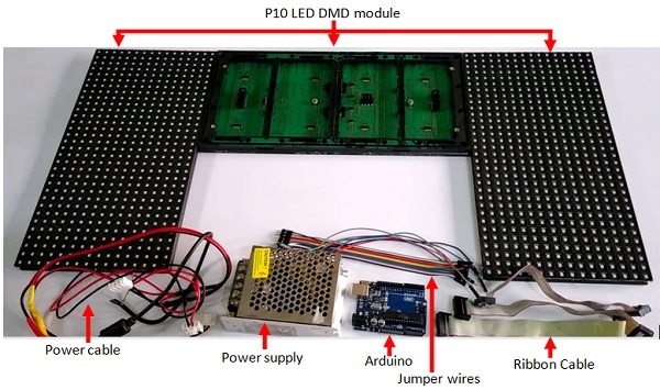
Parts for making a scrolling text display
Arduino Projects, TUTORIALS

How to Design a Digital Scrolling Text Display With Arduino and P10 LED Dot Matrix Display

A digital scrolling text display is an innovative system for showcasing information or announcements on an LED-based board. Whether for advertising, informational purposes, or creative projects, this technology offers an engaging way to display pre-programmed messages. In this tutorial, you’ll learn how to create your own scrolling text display using an Arduino Uno and a P10 LED dot matrix display module. What is a Digital Scrolling Text Display? A digital scrolling text display utilizes an LED array to show text that scrolls across the screen. The data displayed is programmed using a microcontroller, often referred to as a “Control Card.” While there are many types of control cards, the Arduino Uno paired with the Arduino DMD library makes it simple to program and control a P10 LED dot matrix display. P10 LED dot matrix displays come in various colors, allowing for flexibility in design and use. By combining multiple P10 modules, you can create larger displays for bigger projects. Materials Needed To build your scrolling text display, gather the following components: Why Choose Arduino for Scrolling Text Displays? Arduino simplifies the programming process, making it accessible even for beginners. Using the Arduino DMD library, you can easily control the P10 LED modules to create smooth scrolling text effects. This library eliminates the complexity of working directly with the display hardware, allowing you to focus on creativity and functionality. Key Benefits of Building a Scrolling Text Display Steps to Build Your Scrolling Text Display This tutorial walks you through the entire process of connecting your hardware, programming the Arduino Uno, and running the scrolling text display. Circuit diagram of the Scrolling text display with Arduino The DMD library can be downloaded here Here is a step by step tutorial on how to install arduino library. *** Make sure to also download and install the TimerOne library on the Arduino IDE. Arduino Code for Scrolling Text DisplayProject Conclusion Creating a digital scrolling text display using an Arduino Uno and P10 LED dot matrix modules is a rewarding project that combines innovation and practicality. Whether you’re building it for advertisements, event notices, or personal projects, this DIY approach gives you full control over the design and functionality of your display. With the help of the Arduino DMD library, programming and controlling your P10 LED modules becomes simple and efficient. As you experiment with this project, you’ll not only enhance your Arduino skills but also gain a deeper understanding of LED matrix displays and microcontroller programming. We hope this tutorial inspires you to take on new challenges and explore the endless possibilities of Arduino projects. If you have any questions or need further guidance, feel free to leave a comment below. Happy building! If you want to learn practical electronics circuit design, then consider checking out our course: Practical electronics circuit design. This course will teach you everything you need to know to start designing electronics circuits yourself from scratch.

esp32 with micropython
TUTORIALS

Getting Started with Micropython for ESP32 – A Step-by-Step Guide

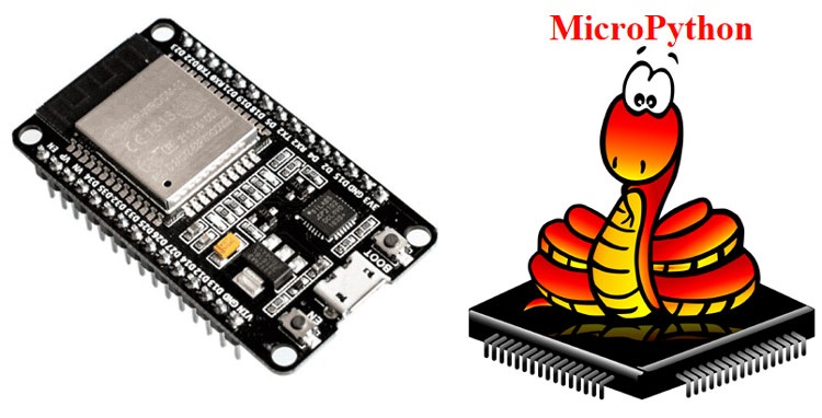
Ever wondered how to bring your Python skills into the world of microcontrollers? With MicroPython and Thonny IDE, turning your ideas into reality has never been easier!. MicroPython and Thonny make it easier than ever to control microcontrollers like the ESP32, Pyboard, ESP8266, WiPy, micro:bit. In this guide, you’ll learn how to set up MicroPython, connect your ESP32 microcontroller to Thonny, and start programming with ease! Why Choose MicroPython and Thonny? MicroPython is a lean and efficient implementation of the Python 3 programming language that is optimized to run on microcontrollers and embedded systems. Thonny, on the other hand, is a beginner-friendly Integrated Development Environment (IDE) for Python that makes it easy to write, run, and debug Python code. Setting Up MicroPython The first step in getting started with MicroPython is to install it on your microcontroller. Many popular microcontrollers, such as the ESP8266 and ESP32 series, support MicroPython. Each microcontroller may have different installation procedures, so this guide is specifically focused on ESP32 series. To set-up micropython for ESP32, follow the steps below Setting Up Thonny IDE Thonny makes it simple for beginners to dive into Python programming, and it’s even better when used with MicroPython. Download Thonny for Windows, macOS, or Linux from the official website, and follow the straightforward installation process. Whether you’re new to coding or an experienced developer, Thonny provides a clean and intuitive environment to write, debug, and run your Python scripts. Download Thonny here and follow the instructions prompt on the screen to finish installation. Installing the CP210x Driver for Windows Before you can start communicating with your ESP32 microcontroller, you’ll need to install the CP210x USB to UART Bridge VCP driver. This driver allows your computer to recognize and communicate with the ESP32 over a USB connection. Be sure to verify the driver is correctly installed by going to your device manager and expanding the PORT section. Why the CP210x Driver is this Important? Without the CP210x driver, your computer might not be able to establish a connection with the ESP32, which can prevent you from uploading code or interacting with the microcontroller. Flashing the ESP32 with esptool via Command Prompt While Thonny offers an easy way to interact with your ESP32, there’s another method that gives you more control over the process—using the command prompt with esptool.py. This approach allows you to manually erase the default firmware and flash new firmware onto your ESP32. Step 1: Install esptool First, you’ll need to install esptool, a Python-based utility for flashing firmware onto Espressif chips like the ESP32. a) Open Command Prompt: b) Install esptool: pip install esptool Step 2: Erase the Default Firmware Before flashing new firmware, it’s recommended to erase the existing firmware. esptool –port COM7 erase_flash IMPORTANT: Hold down the BOOT/FLASH button on the ESP32 while executing this command. This puts the ESP32 into flashing mode. Step 3: Flash the New Firmware  Now that the flash is erased, you can proceed to install the new firmware. (eg. Downloads) using the command cd Downloads Note that this is the folder/directory containing my already downloaded micropython firmware esptool –chip esp32 –port COM7 write_flash -z 0x1000 ESP32_GENERIC-20240222-v1.22.2.bin Again, replace the COM7 with your actual port and the ESP32_GENERIC-20240222-v1.22.2.bin with the name of the firmware you downloaded If the process completes without errors, your ESP32 should now be running the new firmware Now, you are ready to code python on your microcontroller using the Thonny IDE Connecting Thonny to Your Microcontroller Controlling the Onboard LED on the ESP32 Now that you’ve set up MicroPython on your ESP32 and connected it to Thonny, let’s dive into a simple project: controlling an LED. This tutorial will guide you through writing a basic MicroPython script to turn an LED on and off using the GPIO pins on the ESP32. Step 1: Write the MicroPython Script Since you’re using the onboard LED, there’s no need for external components. We’ll go straight into coding. After you have created the python script, click the green play button to run the code immediately, or click the Run button and then click run current script, or you can click F5 to run the script. Once you have done that, Additional Resources For further exploration of MicroPython and Thonny, consider checking out the official documentation for each platform. You can also find a rich community of developers and enthusiasts who can help with any questions or issues you encounter along the way. With this comprehensive guide, you should now have a solid foundation for utilizing MicroPython with Thonny. Whether you’re a beginner or an experienced developer, MicroPython and Thonny provide an accessible platform for programming microcontrollers and embedded systems. Get ready to unleash the power of Python in the world of small-scale computing! Happy coding!

Automatic Water Level controller
Circuit Project Design, TUTORIALS

Automatic Water Level Controller Project

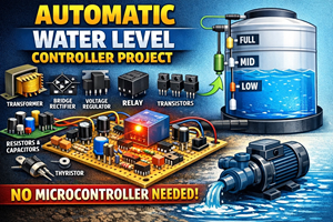
In this detailed tutorial, we’ll explore the process of making a water level controller without the need for a microcontroller. This project serves as an excellent opportunity to deepen your understanding of electronic components and their behaviours in circuits, paving the way for designing complex circuits without relying on microcontrollers like Arduino, PIC, or ESP32. To successfully design such a circuit, it’s crucial to master the behaviours of various electronic components. These components include resistors, capacitors, transistors, relays, thyristors, sensors, transformer, bridge rectifiers, voltage regulators, etc. each playing a vital role in the circuit’s functionality. Understanding how these components interact is key to designing an effective water level controller. For instance, sensors detect the water level and send signals to the circuit. Transistors act as switches, controlling current flow based on sensor input. Resistors and capacitors manage voltage and current flow for stability. Relays switch high-power loads like pumps, thyristors handle power control, transformer and bridge rectifiers convert AC to DC, and voltage regulators maintain a stable output DC voltage. By delving into the intricacies of these components and their roles in circuit design, you’ll not only create a functional water level controller but also gain valuable insights for future projects. This journey of discovery will empower you to design innovative electronic circuits without relying on microcontrollers. List of Materials for the Circuit Design S/N Component Description Quantity 1 Resistor 100R 4 2 Transistor TIP41 3 3 Thyristor BT151 1 4 Transformer 220V to 12V 1 5 Bridge rectifier KBP206 1 6 Capacitor 1000uF, 1uF 2 7 Voltage regulator 7805 1 8 Diode 1N4001 1 9 Relay 5V SPDT 1 10 Jumper wires Male to male  Bunch  Table 1.0 List of Materials for the Circuit Design Images of the electronic components used in the project Tools and Other Materials Used for the Project Parts of the Circuit The project’s circuit consists of two main parts: the power supply and the water level controller.  Power Supply The power supply is responsible for converting AC to DC to provide the necessary electrical energy for the circuit to operate. This is achieved using components such as a transformer, bridge rectifier, capacitors, and voltage regulators. These components work together to ensure a stable DC voltage output, essential for the circuit’s operation. Below is the circuit diagram of the power part of the circuit Water Level Controller On the other hand, the water level controller part of the circuit includes components such as wires serving as sensors, transistors acting as switches, thyristors for current flow control, relays as contactless switches, and resistors and capacitors for managing current flow. These components work in harmony when connected correctly to create an automatic water level controller device. When the water level reaches a certain point, the sensors detect the change and send a signal to the transistors, which act as switches, allowing current to flow through the thyristor. The thyristor then controls the current flow, activating the relay to switch the water pump on or off, maintaining the water level within the desired range. By understanding and appropriately connecting these components, you can create an efficient and reliable automatic water level controller device. Below is the circuit diagram of the water level controller part of the circuit Circuit Diagram and Explanation for the project Below is the complete circuit diagram and explanation of the entire project Circuit Explanation Power Supply Design Breakdown: The circuit starts by converting household current to a usable voltage level, 5V to be precise.. Here’s how it’s done: Water level Controller Circuit Breakdown The circuit utilizes a 5V DC power supply to operate the water level controller. Initially, with no water in the tank, the AC current passes through the normally closed terminal of the relay, powering the pump (represented by an AC bulb and a motor). This indicates that water is being pumped into the tank. When the water touches the two wires at the lower threshold, current from the 5V DC flows through the water and into the base of transistor Q2 via resistor R1. This causes collector current to flow through transistor Q2 and into the anode of the thyristor. However, since the gate of the thyristor is not yet fired, it does not conduct electricity, and current does not flow through it. As the water level reaches the upper threshold of the tank and touches the two wires, current flows from the 5V DC source into the base of transistor Q1 through resistor R2. This causes collector current to flow through transistor Q1 and into the gate of the thyristor via resistor R4, firing the thyristor. Once the thyristor is fired, it conducts, allowing current to flow from its anode to cathode. This current biases transistor Q3, causing collector current to flow through the relay, energizing it. The relay then switches its common (com) terminal from the normally open (NO) to the normally closed (NC) terminal, cutting off the current supply to the pump and stopping water from pumping into the tank. As the water level drops below the upper threshold, the current supply to the thyristor’s gate is cut off. However, since a thyristor continues to conduct even after the firing current is removed, the relay remains energized, and the pump remains off. When the water level falls below the lower threshold, the current to the thyristor’s anode is cut off. This causes the current to the transistor that drives the relay to be cut off as well. With transistor Q3 no longer conducting electricity, the relay de-energizes, returning to its default state. This action allows AC current to flow into the pump, turning it on and restarting the water flow into the tank. This cycle continues as long as there is a power supply, ensuring a continuous water level in the tank. Below is the physical circuit on a breadboard If you’re interested in undertaking this project and need the components used in it, feel free to reach out to us for procurement. Additionally, if you require

Scroll to Top