Ettronics 555 Timer Calculator
Calculate 555 timer astable frequency, monostable delay, 50% duty cycle, PWM values, and practical component suggestions.
Engine 1.0.0
Show formula used
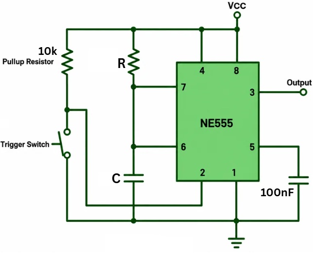
Mode Schematic
Results
Output Waveform
Connection Guide
555 Timer Calculator FAQs
Can a standard 555 astable circuit produce exactly 50% duty cycle?
Not normally. A diode method or divide-by-two flip-flop can be used for a more accurate 50% duty cycle.
What is the recommended resistor range for a 555 timer?
A practical range is often around 1kΩ to 1MΩ, depending on the circuit and timing accuracy required.
Why is my real circuit different from the calculated result?
Capacitor tolerance, resistor tolerance, leakage current, supply voltage, breadboard capacitance, and 555 type can all affect the final result.
If you’re looking for a reliable 555 timer astable calculator or 555 timer monostable calculator, you’ve come to the right place. The 555 timer IC is one of the most popular integrated circuits ever created, and it remains a cornerstone of electronics design for students, hobbyists, technicians, and professional engineers.
From blinking LEDs and alarm circuits to pulse generators and delay timers, the 555 timer offers a simple and cost-effective solution for a wide range of applications. However, manually calculating frequency, duty cycle, pulse width, and timing component values can be tedious and prone to error.
That’s where the Ettronics 555 Timer Calculator comes in. It automatically calculates all the important parameters for both astable and monostable configurations, helping you design accurate circuits faster.
What Is a 555 Timer?
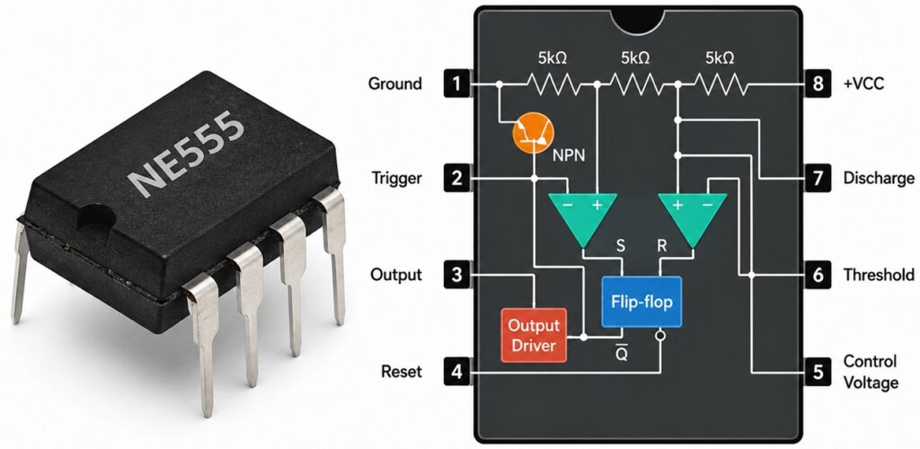
The 555 timer is an eight-pin integrated circuit designed for generating precise timing signals. It can operate in different modes, but the two most commonly used are:
- Astable Mode
- Monostable Mode
In astable mode, the circuit continuously oscillates between HIGH and LOW states.
In monostable mode, the circuit generates a single output pulse whenever it receives a trigger signal.
Because of its simplicity, low cost, and reliability, the 555 timer continues to be used in countless electronic circuits worldwide.
Common applications include:
- LED flashers
- Oscillators
- Pulse generators
- Alarm circuits
- Delay timers
- Frequency generators
- Educational projects
- Industrial control circuits
What Is a 555 Timer Astable Calculator?
A 555 timer astable calculator is a tool used to determine the operating characteristics of a 555 timer configured as a free-running oscillator.
In astable mode, the output continuously alternates between HIGH and LOW without requiring an external trigger.
The calculator automatically computes:
- Frequency
- Period
- High Time
- Low Time
- Duty Cycle
based on the selected resistor and capacitor values.
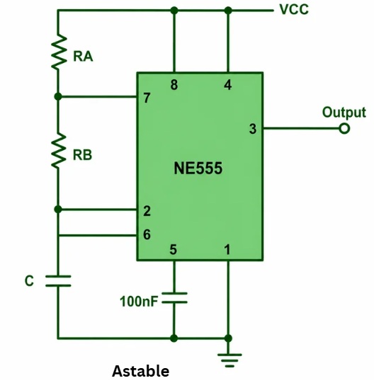
How the Astable Mode Works
In an astable configuration, the timing capacitor repeatedly charges and discharges through the resistor network.
As the capacitor voltage rises and falls between the internal threshold levels of the 555 timer, the output switches state, producing a continuous square-wave signal.
This behavior makes astable mode ideal for:
- LED blinking circuits
- Clock generation
- Signal generation
- Frequency testing
- Oscillators
- Timing applications
555 Timer Astable Formula
The oscillation frequency depends on the values of:
Frequency Formula
Where:
- (f) = Frequency (Hz)
- (RA) = Resistor A (Ω)
- (RB) = Resistor B (Ω)
- (C) = Timing capacitor (F)
Period Formula
Where:
- (T) = Period (seconds)
High Time Formula
Low Time Formula
Duty Cycle Formula
The Ettronics 555 Timer Astable Calculator automatically performs these calculations and presents the results in user-friendly engineering units.
Example Astable Calculation
Suppose you select:
- RA = 10kΩ
- RB = 100kΩ
- C = 10μF
The calculator instantly determines:
- Frequency
- Period
- HIGH duration
- LOW duration
- Duty cycle
without requiring manual calculations.
Practical Uses of Astable Mode
LED Blinkers
Generate flashing LEDs for indicators and warning systems.
Oscillators
Create continuous square-wave signals for testing and timing.
Clock Generators
Provide timing pulses for counters and digital circuits.
Alarm Circuits
Generate repetitive signals for buzzers and sirens.
Educational Demonstrations
Help students understand capacitor charging and discharging behavior.
What Is a 555 Timer Monostable Calculator?
A 555 timer monostable calculator is used to calculate the pulse duration of a one-shot timer circuit.
Unlike astable mode, a monostable circuit remains stable until triggered.
When a trigger signal is applied:
- The output changes state.
- The timing capacitor begins charging.
- The output remains active for a specific duration.
- The circuit automatically returns to its stable state.
This makes monostable mode ideal for generating accurate delays.
How the Monostable Mode Works
In a monostable configuration:
- A trigger pulse initiates the timing cycle.
- The capacitor charges through the timing resistor.
- When the capacitor reaches the threshold voltage, the output resets.
Because only one pulse is generated for each trigger, this configuration is often called a one-shot timer.
555 Timer Monostable Formula
The pulse duration depends on the timing resistor and capacitor.
Pulse Width Formula
Where:
- T = Pulse width (seconds)
- R = Timing resistor (Ω)
- C = Timing capacitor (F)
The Ettronics 555 Timer Monostable Calculator instantly computes the pulse duration based on the selected component values.
Example Monostable Calculation
Suppose you choose:
- R = 100kΩ
- C = 10μF
The pulse width becomes:
Instead of performing these calculations manually, the calculator provides the result instantly.
Astable vs Monostable Mode
| Feature | Astable Mode | Monostable Mode |
|---|---|---|
| Trigger Required | No | Yes |
| Output | Continuous Oscillation | Single Pulse |
| Frequency Generation | Yes | No |
| Delay Generation | Limited | Excellent |
| LED Flashing | Excellent | Limited |
| Oscillator Function | Excellent | No |
| Pulse Generation | Continuous | One-Shot |
Why Use the Ettronics 555 Timer Calculator?
The Ettronics Electronics Calculator platform provides much more than basic calculations.
Real-Time Calculations
Results update automatically as values are entered.
Formula Display
View the actual equations used for each calculation.
Engineering Unit Conversion
Convert values between:
- Hz
- kHz
- MHz
- Seconds
- Milliseconds
- Microseconds
- Ohms
- Kilohms
- Megaohms
Circuit Schematics
Visual diagrams help users understand circuit connections.
Mobile-Friendly Interface
Designed to work perfectly on phones, tablets, and desktop computers.
Educational Explanations
Learn how the calculations are derived while designing your circuit.
Common 555 Timer Design Mistakes
Choosing Extremely Large Capacitors
Large electrolytic capacitors can introduce leakage errors.
Using Very Small Resistor Values
Low resistance values may overload the discharge transistor.
Ignoring Power Supply Decoupling
A 100 nF capacitor between VCC and GND helps improve stability.
Leaving the Reset Pin Floating
Pin 4 should typically be connected to VCC.
Ignoring Duty Cycle Limitations
Standard astable circuits cannot naturally produce a perfect 50% duty cycle without modifications.
Understanding Duty Cycle
Duty cycle describes the percentage of time the output remains HIGH during one complete cycle.
The formula is:
Where:
- D = Duty cycle
- TH = High time
- TL = Low time
This parameter is particularly important in oscillator and pulse generation applications.
Who Should Use a 555 Timer Calculator?
The calculator is ideal for:
- Electronics students
- Engineering students
- Hobbyists
- Repair technicians
- Circuit designers
- STEM educators
- Makers and inventors
Whether you are designing a simple LED flasher or a complex timing circuit, accurate calculations help ensure reliable performance.
Final Thoughts
A dependable 555 timer astable calculator and 555 timer monostable calculator can significantly simplify the design process.
Instead of manually solving equations, converting units, and checking calculations, the Ettronics 555 Timer Calculator provides instant results for frequency, duty cycle, pulse width, high time, low time, and timing component selection.
By combining real-time calculations, engineering unit conversion, mathematical formulas, educational explanations, and circuit schematics, the calculator serves as both a practical design tool and a learning resource for anyone interested in electronics.
Whether your goal is to build an oscillator, delay timer, pulse generator, or timing circuit, the Ettronics 555 Timer Calculator provides the accuracy and convenience needed to bring your design to life.
See more Calculators: