Have you ever built a circuit, repaired an amplifier, or worked on an electronics project only to discover that it simply refuses to work? In many cases, one small component can be responsible: the transistor.
Transistors are among the most commonly used components in electronics, and because they are used as switches and amplifiers in almost every modern circuit, a faulty transistor can stop an entire system from functioning correctly.
The good news is that you do not need expensive equipment to test one. A standard digital multimeter can quickly help you determine whether a transistor is healthy or damaged.
In this guide, you will learn:
- What a transistor is
- Tools needed for testing
- How to identify transistor pins
- How to test NPN transistors
- How to test PNP transistors
- How to identify a faulty transistor
- Common mistakes to avoid
Let’s begin.
What Is a Transistor?
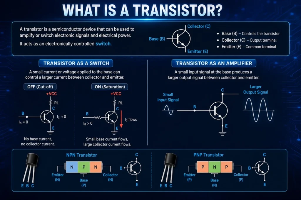
A transistor is a semiconductor device used to control electrical current. It mainly serves two functions:
- Switching electronic signals ON and OFF
- Amplifying electrical signals
You can think of a transistor as an electronically controlled switch. A small current entering one terminal can control a larger current flowing through the other terminals.
Most beginners will commonly encounter two major transistor types:
- NPN transistor
- PNP transistor
Both types typically have three terminals:
- Base (B)
- Collector (C)
- Emitter (E)
Testing either type with a multimeter is relatively similar, although the probe connections differ.
Tools Needed
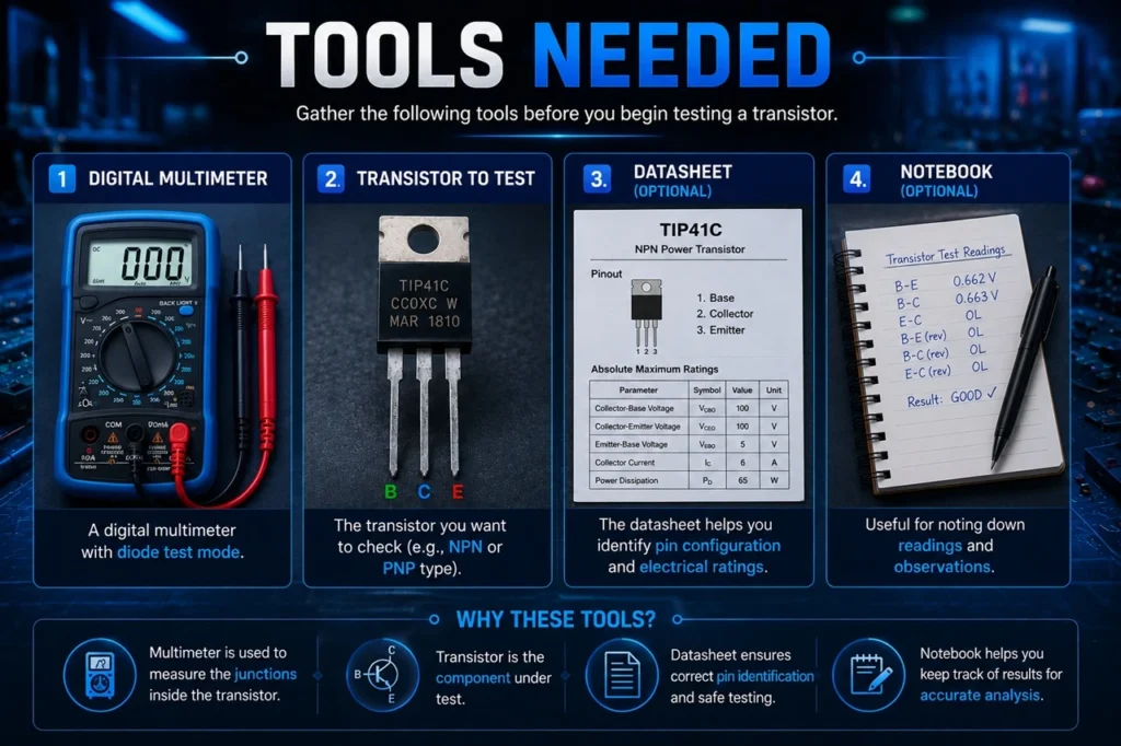
Before you begin, gather the following:
- Digital multimeter
- Transistor to test
- Transistor datasheet (optional but recommended)
- Notebook for recording readings (optional)
A digital multimeter with diode mode is highly recommended because it provides more reliable results than continuity mode.
Safety Precautions Before Testing
Before testing any transistor:
- Disconnect all power from the circuit
- Remove batteries if present
- Discharge capacitors in the circuit
- Remove the transistor from the circuit when possible
Testing a transistor while it remains connected in a circuit may produce incorrect readings because nearby components can affect measurements.
Identify the Transistor Pins First
Before placing multimeter probes on a transistor, you need to identify its terminals:
- Base
- Collector
- Emitter
Different transistors may have different pin arrangements.
For example:
A TIP41 transistor may use:
| Pin | Function |
|---|---|
| 1 | Base |
| 2 | Collector |
| 3 | Emitter |
Another transistor may use a different arrangement.
The safest approach is checking the transistor datasheet before testing.
Understanding Diode Mode on a Multimeter
Most digital multimeters have a diode test mode.
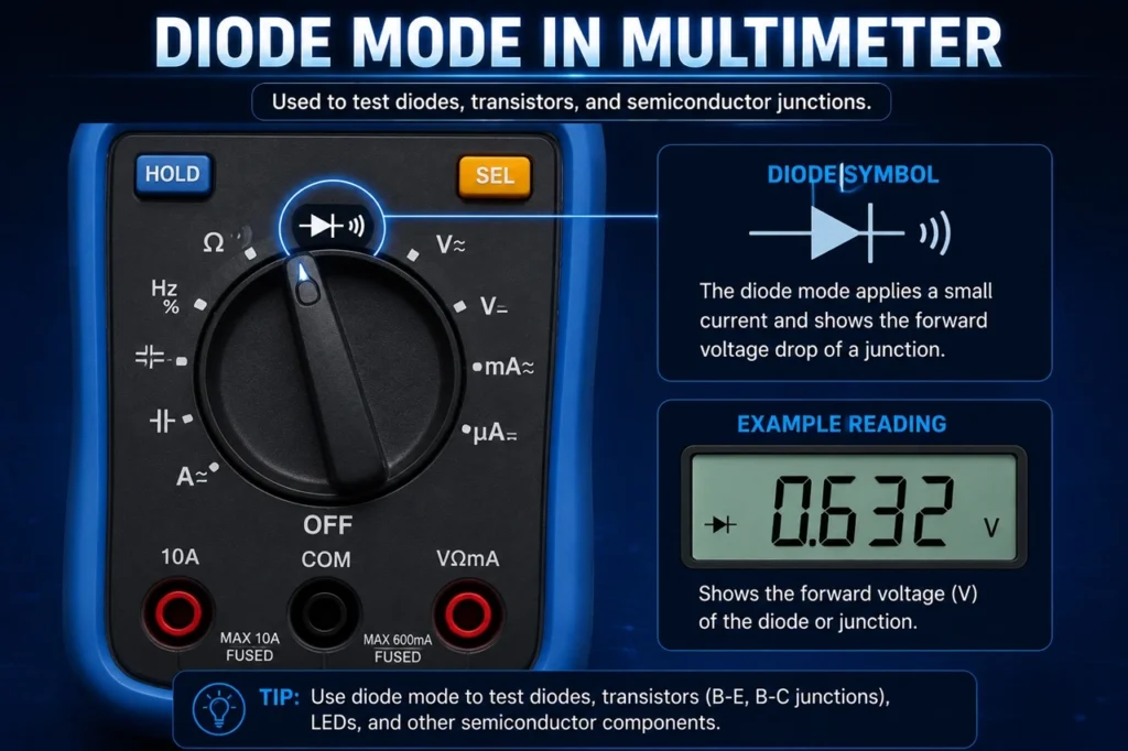
Diode mode measures the voltage drop across semiconductor junctions.
Since a transistor contains two PN junctions internally, testing a transistor in diode mode effectively tests those junctions.
For a healthy transistor, typical readings are:
- Approximately 0.5V–0.8V in forward bias
- OL (open loop) or very high resistance in reverse bias
How to Test an NPN Transistor Using a Multimeter
Watch video below.
Follow these steps carefully.
Step 1: Set Your Multimeter to Diode Mode
Rotate the multimeter dial to diode test mode.
Step 2: Connect the Red Probe to the Base
Place:
- Red probe → Base
- Black probe → Emitter
Observe the reading.
A good transistor should display approximately:
0.5V–0.8V
Step 3: Move Black Probe to Collector
Keep:
- Red probe → Base
- Black probe → Collector
Expected reading:
0.5V–0.8V
Step 4: Reverse the Probe Connections
Now reverse the probes:
- Black probe → Base
- Red probe → Emitter
Expected reading:
OL
Repeat:
- Black probe → Base
- Red probe → Collector
Expected reading:
OL
Step 5: Test Collector to Emitter
Measure directly between:
- Collector
- Emitter
Expected reading:
OL in both directions
If you obtain very low resistance or a short-circuit reading, the transistor is likely damaged.
Expected NPN Readings
| Test Connection | Healthy Reading |
|---|---|
| Base → Emitter | 0.5V–0.8V |
| Base → Collector | 0.5V–0.8V |
| Reverse Base → Emitter | OL |
| Reverse Base → Collector | OL |
| Collector → Emitter | OL |
How to Test a PNP Transistor Using a Multimeter
Testing a PNP transistor is almost identical except that probe polarity changes.
Step 1
Set multimeter to diode mode.
Step 2
Connect:
- Black probe → Base
- Red probe → Emitter
Expected reading:
0.5V–0.8V
Step 3
Keep:
- Black probe → Base
- Red probe → Collector
Expected reading:
0.5V–0.8V
Step 4
Reverse probe connections.
Expected reading:
OL
Expected PNP Readings
| Test Connection | Healthy Reading |
|---|---|
| Base → Emitter | 0.5V–0.8V |
| Base → Collector | 0.5V–0.8V |
| Reverse Base → Emitter | OL |
| Reverse Base → Collector | OL |
| Collector → Emitter | OL |
How to Know if a Transistor Is Bad
A faulty transistor often produces unusual readings.
Signs include:
1. Short Circuit Reading
If you measure near zero resistance in both directions:
- Base ↔ Collector
- Base ↔ Emitter
- Collector ↔ Emitter
The transistor may be shorted internally.
2. Open Circuit Everywhere
If every measurement shows:
OL
The transistor junctions may be damaged.
3. Collector and Emitter Are Shorted
Collector and emitter should not normally behave like a wire.
If they do, the transistor is likely defective.
4. Inconsistent Readings
Readings that change dramatically each time you test can indicate a damaged transistor.
Common Mistakes When Testing a Transistor
Many beginners make these mistakes:
Testing While the Circuit Is Powered
Always disconnect power first.
Using Continuity Mode Instead of Diode Mode
Continuity mode may not provide accurate transistor measurements.
Wrong Pin Identification
Incorrectly identifying Base, Collector, or Emitter can produce confusing results.
Always verify with the datasheet.
Testing While Component Is Still on the Circuit Board
Nearby components may interfere with readings.
Remove the transistor whenever possible.
Frequently Asked Questions
Can I test a transistor without removing it from the circuit?
Yes, but the readings may not be accurate because surrounding components can affect the measurement.
Can a transistor appear good and still fail?
Yes.
A transistor may pass simple multimeter tests but fail when operating under actual load conditions.
Can an analog multimeter test a transistor?
Yes.
However, digital multimeters are generally easier and more accurate.
Can a multimeter identify transistor type automatically?
Some multimeters include transistor testing sockets that can automatically identify transistor characteristics.
Final Thoughts
Knowing how to test a transistor using a multimeter is one of the most useful skills in electronics troubleshooting and repair. Whether you are building DIY projects, repairing devices, or learning electronics for the first time, this simple procedure can save time and prevent unnecessary component replacement.
Once you become comfortable testing transistors, the next step is learning how to test other electronic components using the same multimeter.
You may also want to read:
- Difference Between Analog and Digital Electronics with Practical Examples
- How to Design a Digital Scrolling Text Display With Arduino and P10 LED Dot Matrix Display
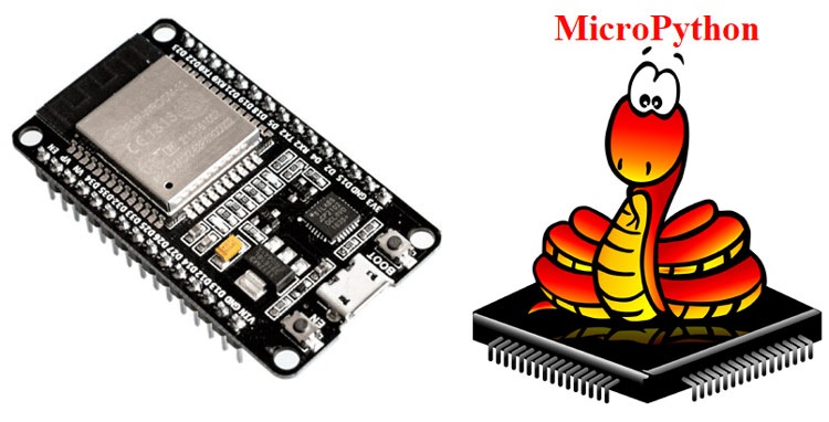
- Getting Started with Micropython for ESP32 – A Step-by-Step Guide
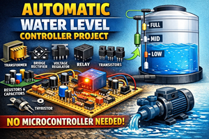
- Automatic Water Level Controller Project
Mastering these basic troubleshooting skills will make diagnosing electronic circuits much easier and faster. If you want to learn practical electronics circuit design, check out our practical course