Voltage Divider Calculator helps you quickly determine the output voltage produced by two resistors connected in series. Instead of performing manual calculations, this tool can calculate the input voltage (Vin), output voltage (Vout), or resistor values (R1 and R2) required to achieve a desired voltage.
Use the calculator below to instantly solve voltage divider problems and obtain accurate results.
Ettronics Electronics Calculator
Voltage Divider Calculator
Calculate Vin, Vout, R1, or R2 in a two-resistor voltage divider circuit.
Enter Known Values
Voltage Divider Circuit Diagram
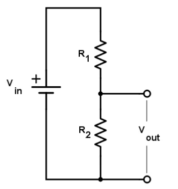
Vout is taken from the junction between R1 and R2, measured across R2 to ground.
Engineering Result Display
What this calculator does
This tool calculates the relationship between Vin, Vout, R1, and R2 in a standard two-resistor voltage divider.
When to use a voltage divider
Use it for signal scaling, reference voltages, sensor interfaces, ADC input scaling, and simple low-current bias circuits.
Important warning
A voltage divider is not a proper power supply for heavy loads. If the load current is high, use a regulator or DC-DC converter instead.
What Is a Voltage Divider?
A voltage divider is a simple electronic circuit that uses two resistors connected in series to produce a lower voltage from a higher input voltage.
The output voltage is taken from the junction between the two resistors.
Voltage dividers are commonly used when a circuit requires a voltage level that is lower than the available supply voltage.
For example:
- Converting 12V to 5V reference levels
- Scaling sensor outputs
- Interfacing sensors with microcontrollers
- ADC input voltage scaling
- Creating reference voltage
Voltage Divider Formula
The voltage divider formula is:
Where:
- Vin = Input voltage
- Vout = Output voltage
- R1 = Upper resistor
- R2 = Lower resistor
The formula shows that the output voltage depends on the ratio between the two resistor values.
How to Use the Voltage Divider Calculator
Using the calculator is straightforward:
Step 1
Select what you want to calculate:
- Vin
- Vout
- R1
- R2
Step 2
Enter the known values.
Step 3
Select the appropriate units.
Step 4
Click Calculate.
Step 5
Review the results and recommendations.
Example Voltage Divider Calculation
Suppose:
- Vin = 12V
- R1 = 10kΩ
- R2 = 5kΩ
Applying the formula:
Result:
Vout = 4V
This means a 12V supply can be reduced to approximately 4V using these resistor values.
Common Applications of Voltage Dividers
Voltage dividers are used in countless electronic circuits.
Sensor Interfacing
Many sensors output voltages that must be scaled before entering a microcontroller.
Examples:
- Temperature sensors
- Light sensors
- Gas sensors
ADC Input Scaling
Microcontrollers such as:
- Arduino
- ESP32
- Raspberry Pi Pico
often have voltage limitations on their analog inputs.
Voltage dividers help reduce higher voltages to safe levels.
Reference Voltage Generation
Voltage dividers can create stable reference voltages for:
- Comparators
- Operational amplifiers
- Analog circuits
Battery Monitoring
Battery voltages frequently exceed the safe input range of ADC pins.
Voltage dividers are commonly used to monitor battery levels safely.
Advantages of Voltage Dividers
- Simple design
- Low cost
- Easy to build
- Requires only two resistors
- Suitable for many low-current applications
Limitations of Voltage Dividers
Although useful, voltage dividers have limitations.
Load Effects
Connecting a load to the output changes the effective resistance and may alter the output voltage.
Not Suitable for High Current Loads
Voltage dividers are intended for signal-level applications rather than powering devices.
Reduced Accuracy
Resistor tolerances affect output voltage accuracy.
Using 1% resistors generally produces better results than 5% resistors.
Common Voltage Divider Mistakes
Using Incorrect Resistor Values
Always verify resistor values before assembly.
Ignoring Resistor Tolerance
Resistors are not perfect and can vary from their nominal value.
Forgetting Load Resistance
The connected circuit can significantly affect the output voltage.
Using a Voltage Divider as a Power Supply
Voltage dividers are not designed to power heavy loads.
Practical Design Tips
- Use 1% resistors for improved accuracy.
- Keep resistor values within a practical range.
- Avoid excessively large resistor values in noisy environments.
- Verify results using a multimeter.
- Consider load effects during design.
Frequently Asked Questions
What does a voltage divider do?
A voltage divider reduces an input voltage to a lower output voltage using two resistors connected in series.
Can a voltage divider increase voltage?
No. A voltage divider can only reduce voltage.
What happens if R1 equals R2?
When R1 and R2 have the same value, the output voltage becomes half of the input voltage.
Why is my measured output voltage different from the calculated value?
Possible reasons include:
- Resistor tolerance
- Load resistance
- Measurement errors
- Incorrect resistor values
Can I use a voltage divider with an Arduino or ESP32?
Yes. Voltage dividers are commonly used to scale voltages for Arduino and ESP32 analog input pins.
Final Thoughts
A voltage divider is one of the most important circuits in electronics. Understanding how it works can help you design sensor interfaces, scale voltages for microcontrollers, generate reference voltages, and troubleshoot electronic circuits more effectively.
Use the Voltage Divider Calculator above whenever you need to quickly determine Vin, Vout, R1, or R2 without performing manual calculations.
Whether you are an electronics student, hobbyist, maker, technician, or engineer, voltage dividers are among the most frequently used circuits in electronic design.
For more electronics tools, explore our growing collection of calculators and tutorials on Ettronics.