Arduino LED Blink Tutorial for Beginners (Step-by-Step Guide)
Learning to program an Arduino is one of the most exciting ways to begin your journey into electronics, robotics, and embedded systems. If you’ve never written a line of code before, don’t worry, this tutorial is designed specifically for beginners, children, parents, teachers, and aspiring innovators who want to learn through practical, hands-on projects.
In this lesson, you’ll build one of the most famous beginner projects in electronics: the Arduino LED Blink Project. Although it may seem simple, this project introduces nearly every fundamental concept you’ll use in future Arduino programming, including writing code, uploading programs to a microcontroller, controlling digital outputs, and understanding how a program executes continuously.
Whether your goal is to build robots, smart home systems, IoT devices, automation projects, or simply learn programming from scratch, the LED Blink project is the perfect place to start.
This tutorial is part of our Coding with Arduino for Young Innovators series, where every lesson builds practical skills through easy-to-understand explanations and exciting projects.
Why Every Beginner Starts with the LED Blink Project
If you’ve ever searched online for beginner Arduino projects, you’ve probably noticed that almost everyone starts with blinking an LED. That’s not because it’s the easiest project, it’s because it teaches almost every basic programming concept you’ll need later.
By completing this project, you’ll learn how to:
- Install the Arduino IDE
- Connect an Arduino UNO R3 to your computer
- Write your very first Arduino program
- Upload code to your Arduino board
- Control an electronic component using software
- Understand how Arduino executes instructions
- Modify your program to change the LED blinking speed
These skills become the foundation for more advanced projects involving sensors, LCD displays, motors, Bluetooth, Wi-Fi, IoT, and robotics.
What You Will Learn
By the end of this tutorial, you will understand:
- What Arduino programming is
- How the Arduino UNO R3 works
- How to install the Arduino IDE
- How to connect your Arduino to your computer
- How to configure the Arduino IDE
- How to build a simple LED circuit
- How to upload your first Arduino program
- How the
setup()andloop()functions work - How to modify the blinking speed
- How to troubleshoot common beginner mistakes
If this is your very first Arduino project, you’re in the right place.
What Is Arduino?
Arduino is an open-source electronics platform that combines both hardware and software to make programming electronic devices simple and accessible.
Instead of designing complex electronic circuits from scratch, Arduino provides a programmable microcontroller board that can interact with the outside world. By writing a few lines of code, you can control LEDs, motors, sensors, displays, relays, and many other electronic components.
The Arduino platform has become one of the most popular learning tools for:
- Students
- Hobbyists
- Teachers
- Engineers
- Makers
- Robotics enthusiasts
- IoT developers
One reason Arduino is so popular is its simplicity. Even someone with no programming experience can build useful projects within a few hours.
What Is the Arduino UNO R3?
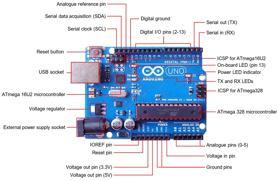
For this lesson, we’re using the Arduino UNO R3, one of the most popular development boards in the world.
The Arduino UNO R3 is powered by the ATmega328P microcontroller, which acts as the “brain” of the board. It executes the programs you upload and controls the connected electronic components.
Some key features of the Arduino UNO R3 include:
- 14 Digital Input/Output Pins
- 6 Analog Input Pins
- USB Programming Interface
- 16 MHz Clock Speed
- 32 KB Flash Memory
- 5V Operating Voltage
- Reset Button
- Power Jack
These features make the Arduino UNO R3 ideal for learning electronics and programming.
As you progress through this course, you’ll use these pins to connect sensors, buzzers, LCDs, ultrasonic modules, Bluetooth devices, Wi-Fi modules, and much more.
What Is an LED?
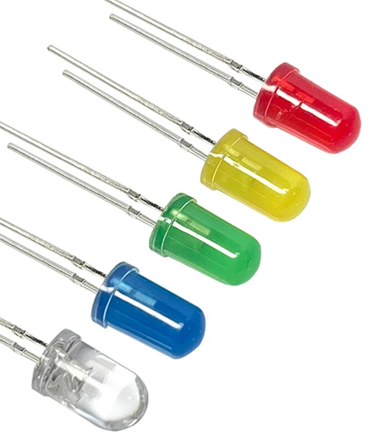
An LED (Light Emitting Diode) is a small electronic component that emits light when electrical current flows through it.
Unlike ordinary light bulbs, LEDs consume very little power while producing bright light, making them ideal for electronic projects.
LEDs come in many colors, including:
- Red
- Green
- Blue
- Yellow
- White
- Orange
An LED has two legs:
Long Leg (Anode)
The longer leg is the positive terminal and should be connected toward the positive voltage through a current-limiting resistor.
Short Leg (Cathode)
The shorter leg is the negative terminal and is connected to Ground (GND).
If you connect the LED backward, it will not light up because LEDs only allow current to flow in one direction.
Why Do We Need a Resistor?
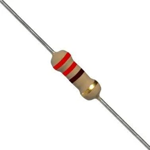
One of the biggest mistakes beginners make is connecting an LED directly to an Arduino pin.
This can allow too much current to flow through the LED, potentially damaging both the LED and the Arduino’s output pin.
To prevent this, we use a 220 Ω to 330 Ω resistor in series with the LED. You can check out our resistor calculator software.
The resistor limits the current flowing through the LED, ensuring safe operation while maintaining sufficient brightness.
Think of the resistor as a traffic controller, it slows the flow of electrical current to a safe level.
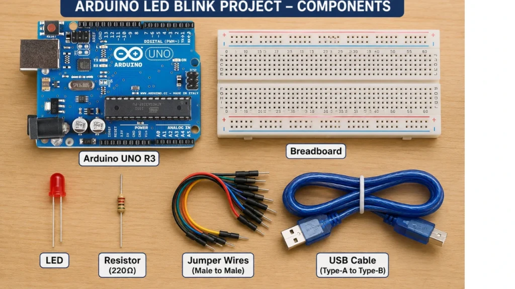
Components Required
To complete this project, you’ll need the following components:
| Component | Quantity |
|---|---|
| Arduino UNO R3 | 1 |
| Breadboard | 1 |
| LED | 1 |
| 220 Ω or 330 Ω Resistor | 1 |
| Jumper Wires | 2–3 |
| USB Type A to Type B Cable | 1 |
| Computer with Arduino IDE | 1 |
These components are inexpensive and form the basis of countless Arduino projects.
Installing the Arduino IDE
Before you can program your Arduino UNO R3, you need to install the Arduino Integrated Development Environment (IDE). The Arduino IDE is the software used to write, compile, and upload code to your Arduino board.
The Arduino IDE is beginner-friendly and works on Windows, macOS, and Linux. It provides a simple code editor, tools for selecting your board and communication port, and a built-in serial monitor for debugging.
Step 1: Download the Arduino IDE
Visit the official Arduino website and download the latest version of the Arduino IDE that matches your operating system.
Choose the installer for:
- Windows
- macOS
- Linux
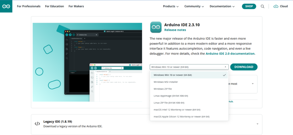
Once the download is complete, run the installer and follow the on-screen instructions.
Step 2: Install the Software
After downloading:
- Double-click the installer.
- Accept the license agreement.
- Leave the default installation options selected.
- Click Install.
- Wait for the installation to finish.
- Launch the Arduino IDE.
The installation process usually takes only a few minutes.
Connecting the Arduino UNO R3 to Your Computer
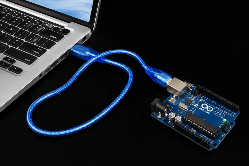
After installing the Arduino IDE, it’s time to connect your Arduino board.
Use a USB Type-A to Type-B cable (often called a printer USB cable).
Plug:
- The USB Type-B end into the Arduino UNO R3.
- The USB Type-A end into your computer.
If everything is connected correctly:
- The ON power LED on the Arduino should light up.
- Your computer should recognize the board automatically.
Configuring the Arduino IDE
Before uploading your program, you must tell the Arduino IDE which board you’re using and which communication port it is connected to.
Selecting the Board
In the Arduino IDE:
- Click Tools.
- Select Board.
- Choose Arduino AVR Boards.
- Click Arduino Uno.
This ensures the IDE compiles your code for the correct microcontroller.
Selecting the COM Port
Next:
- Click Tools.
- Select Port.
- Choose the COM port associated with your Arduino.
If you’re unsure which port is correct:
- Disconnect the Arduino.
- Observe which COM port disappears.
- Reconnect it.
- The port that reappears is your Arduino.
Selecting the wrong port will prevent the IDE from uploading your code.
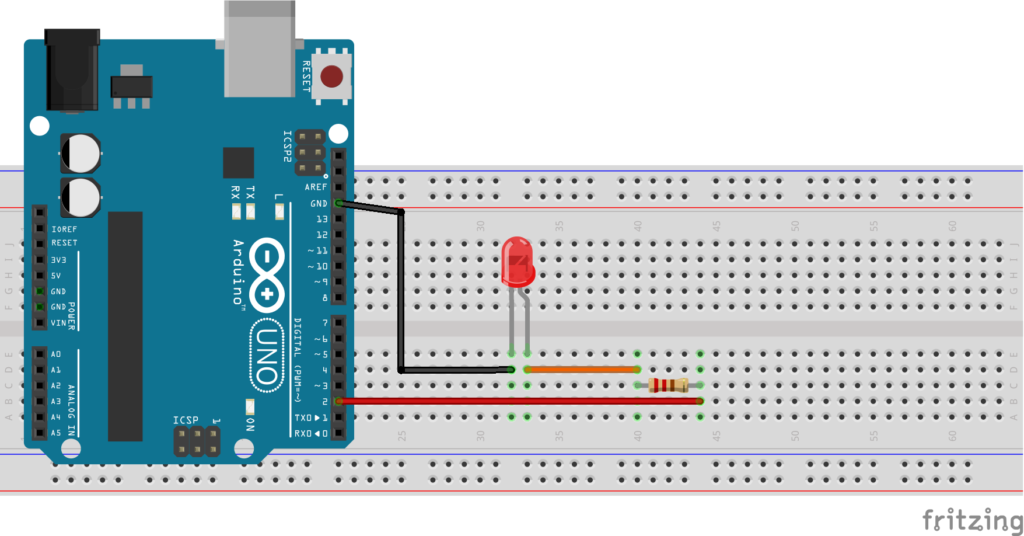
Building the LED Blink Circuit
Now comes the fun part, building your first electronic circuit.
Although the Arduino UNO includes a built-in LED connected to digital pin 13, using an external LED helps you understand how electronic components are connected on a breadboard.
Circuit Connections
Make the following connections:
| Arduino Pin | Connects To |
|---|---|
| Digital Pin 2 | 220 Ω resistor |
| Other end of resistor | LED anode (long leg) |
| LED cathode (short leg) | GND |
This creates a simple series circuit where the Arduino controls the flow of current through the LED.
Understanding the Circuit
When Digital Pin 2 outputs HIGH (5V):
- Electrical current flows through the resistor.
- The LED receives power.
- The LED lights up.
When Pin 2 outputs LOW (0V):
- Current stops flowing.
- The LED turns off.
The Arduino repeats this process continuously, creating the blinking effect.
Understanding Arduino Programming
Before writing any code, it’s important to understand how an Arduino program is organized.
Every Arduino sketch contains two essential functions:
void setup()
{

}

void loop()
{

}
These two functions are mandatory. Without them, your program will not compile.
What Is the setup() Function?
The setup() function runs only once when:
- the Arduino is powered on,
- the reset button is pressed, or
- a new program is uploaded.
It is used to configure the Arduino before the main program starts.
Typical tasks performed in setup() include:
- Setting pin modes
- Initializing serial communication
- Starting sensors
- Initializing LCD displays
- Configuring communication modules
In our LED project, we use setup() to tell the Arduino that Pin 2 will be used as an output.
pinMode(2, OUTPUT);This instruction prepares the Arduino to send voltage through Pin 2.
What Is the loop() Function?
Unlike setup(), the loop() function runs repeatedly for as long as the Arduino has power.
The Arduino executes the code inside loop() over and over again.
Imagine reading a book where, after reaching the last page, you immediately return to page one and start reading again. That’s essentially how the loop() function works.
For the LED blink project, the Arduino repeatedly:
- Turns the LED on.
- Waits.
- Turns the LED off.
- Waits.
- Starts again.
This continuous cycle creates the blinking effect.
Writing Your First Arduino Program
Now it’s time to write your very first Arduino sketch.
Type the following code into the Arduino IDE:
void setup()
{
  pinMode(2, OUTPUT);
}

void loop()
{
  digitalWrite(2, HIGH);
  delay(1000);

  digitalWrite(2, LOW);
  delay(1000);
}
Congratulations! You’ve just written your first Arduino program.
Understanding the Program
Let’s break down what each line of code does.
pinMode(2, OUTPUT);
This line tells the Arduino that Pin 13 will be used to send electrical signals out to the LED.
Without this instruction, the Arduino would not know whether Pin 2 should behave as an input or an output.
digitalWrite(2, HIGH);
This command sends 5 volts to Digital Pin 2.
As a result:
- Current flows through the resistor.
- The LED lights up.
delay(1000);
The delay() function pauses the program.
The value inside the parentheses is measured in milliseconds.
For example:
- 1000 = 1 second
- 500 = 0.5 seconds
- 200 = 0.2 seconds
So, delay(1000); keeps the LED on for one second.
digitalWrite(2, LOW);
This command turns off Pin 2 by setting it to 0 volts.
Current stops flowing through the LED, causing it to switch off.
The Second delay(1000);
After turning the LED off, the Arduino waits another second before repeating the process.
This creates a blinking pattern of:
- 1 second ON
- 1 second OFF
- Repeat forever
Verifying Your Arduino Program
Before uploading your code to the Arduino UNO R3, it’s a good practice to verify it. Verifying checks your code for syntax errors without sending it to the board.
In the Arduino IDE:
- Click the Verify button (✓) in the toolbar.
- Wait for the IDE to compile your code.
- If there are no errors, you’ll see a message such as:
Done compiling.
If the IDE reports an error, read the message carefully. Common issues include:
- Missing semicolons (
;) - Misspelled function names
- Missing opening or closing braces (
{})
Fix any errors before proceeding to upload.
Uploading the Code to the Arduino UNO R3
Once your program has been verified successfully, you’re ready to upload it to the Arduino board.
Follow these steps:
- Ensure your Arduino UNO R3 is connected to your computer.
- Confirm that the correct board and COM port are selected.
- Click the Upload button (→) in the Arduino IDE.
- Wait while the IDE compiles and uploads the sketch.
During the upload process, you may notice the TX and RX LEDs on the Arduino flashing. This indicates that data is being transferred between your computer and the board.
When the upload is complete, the IDE will display:
Done uploading.
At this point, your Arduino begins running the program immediately.
What Should You See?
If everything is connected correctly, your external LED should:
- Turn on for one second.
- Turn off for one second.
- Repeat this cycle continuously.
Congratulations! You’ve successfully programmed a microcontroller and completed your first Arduino project.
This blinking LED may seem simple, but it’s a significant achievement. You’ve written code, compiled it, uploaded it to hardware, and controlled an electronic component using software.
How the LED Blink Program Works
Let’s look at the sequence of events that occurs once the program starts:
- The Arduino powers on.
- The
setup()function runs once and configures Pin 2 as an output. - The
loop()function begins executing. - Pin 2 is set HIGH, turning the LED on.
- The Arduino waits for one second.
- Pin 2 is set LOW, turning the LED off.
- The Arduino waits for another second.
- The
loop()function repeats indefinitely.
This continuous cycle is what creates the blinking effect.
Changing the Blinking Speed
One of the easiest ways to experiment with your program is by changing the delay values.
The delay() function accepts a value in milliseconds, where:
- 1000 milliseconds = 1 second
- 500 milliseconds = 0.5 seconds
- 250 milliseconds = 0.25 seconds
- 100 milliseconds = 0.1 seconds
For example, to make the LED blink twice as fast, modify the code as follows:
void setup()
{
  pinMode(2, OUTPUT);
}

void loop()
{
  digitalWrite(2, HIGH);
  delay(500);

  digitalWrite(2, LOW);
  delay(500);
}
Now the LED will remain on for half a second and off for half a second, resulting in a faster blinking pattern.
You can experiment with different delay values to observe how they affect the LED’s behavior. This is a great way to become familiar with timing in Arduino programming.
Understanding Milliseconds
The delay() function uses milliseconds rather than seconds. Understanding this unit of time is important because many Arduino functions rely on milliseconds.
Here are some common conversions:
| Milliseconds | Time Equivalent |
|---|---|
| 100 | 0.1 second |
| 250 | 0.25 second |
| 500 | 0.5 second |
| 1000 | 1 second |
| 2000 | 2 seconds |
| 5000 | 5 seconds |
Knowing these conversions will help you create projects with precise timing, such as traffic lights, alarms, and automated systems.
Common Beginner Mistakes and How to Fix Them
It’s normal to encounter a few issues when working on your first Arduino project. Here are some common problems and their solutions.
1. The LED Doesn’t Turn On
Possible causes:
- The LED is connected backward.
- The resistor is not connected properly.
- A jumper wire is loose.
- The Arduino isn’t powered.
Solution: Check that the LED’s long leg (anode) is connected through the resistor to Pin 13, and the short leg (cathode) is connected to GND.
2. Upload Fails
Possible causes:
- Incorrect board selected.
- Wrong COM port selected.
- Faulty USB cable.
- Another program is using the COM port.
Solution: Verify the board and port settings in the Arduino IDE and ensure you’re using a data-capable USB cable.
3. Compilation Errors
Possible causes:
- Missing semicolons.
- Misspelled commands.
- Missing braces.
Solution: Read the error messages carefully. They often indicate the line number where the issue occurred.
4. The LED Stays On Constantly
Possible causes:
- The
digitalWrite(2, LOW);line is missing. - The second
delay()function has been removed. - The code wasn’t uploaded successfully.
Solution: Compare your sketch with the example provided and upload it again.
5. Arduino Is Not Detected by the Computer
Possible causes:
- USB cable only supports charging.
- Drivers are missing.
- Loose USB connection.
Solution: Try another USB port or use a known data-capable USB cable.
Why the LED Blink Project Is So Important
Although it involves only a single LED, this project introduces several core concepts you’ll use in nearly every Arduino application.
By completing this lesson, you’ve learned how to:
- Write your first Arduino program.
- Configure digital pins.
- Control an output device.
- Upload code to a microcontroller.
- Use timing with the
delay()function. - Understand the flow of an Arduino program.
These concepts are the building blocks for more advanced projects involving:
- Push buttons
- Buzzers
- LCD displays
- Ultrasonic sensors
- Servo motors
- Temperature sensors
- Bluetooth modules
- Wi-Fi-enabled devices
- Internet of Things (IoT) applications
- Robotics
As you continue learning, you’ll discover that many projects use the same programming structure introduced in this lesson. Mastering these fundamentals now will make it much easier to understand and build more complex systems later.
Real-World Applications of the LED Blink Concept
At first glance, blinking an LED may seem like a simple exercise. However, the same programming principles are used in many real-world electronic systems.
When engineers design electronic products, they often use LEDs to indicate system status. For example:
- A Wi-Fi router uses LEDs to show internet connectivity.
- A computer uses LEDs to indicate power and hard drive activity.
- A television uses LEDs to show whether it is in standby mode.
- Industrial control systems use LEDs to indicate faults or operating conditions.
- Medical equipment uses LEDs to display operational status.
The same HIGH, LOW, and timing concepts learned in this project are used in these professional systems.
As you continue your Arduino journey, you’ll discover that the blinking LED project is the foundation for many advanced applications.
Skills You Have Learned in This Lesson
By completing this project, you have successfully learned:
✅ How to install the Arduino IDE
✅ How to connect an Arduino UNO R3 to a computer
✅ How to configure the Arduino IDE
✅ How to build a simple LED circuit
✅ How to write your first Arduino program
✅ How to upload code to a microcontroller
✅ How the setup() function works
✅ How the loop() function works
✅ How to use digitalWrite()
✅ How to use the delay() function
✅ How to modify timing values
✅ How software controls electronic hardware
These are the same foundational skills used by engineers, makers, robotics enthusiasts, and IoT developers worldwide.
Tips for Young Innovators
If you’re a student or beginner learning Arduino for the first time, here are some helpful tips:
Experiment with the Code
Don’t be afraid to change values and observe what happens.
Try:
- Faster blinking
- Slower blinking
- Different timing patterns
Experimentation is one of the fastest ways to learn programming.
Learn by Building Projects
Reading about electronics is useful, but building projects is where real learning happens.
Each new project introduces new concepts and challenges that improve your problem-solving skills.
Keep a Project Notebook
Professional engineers document their work.
Consider keeping a notebook where you record:
- Circuit diagrams
- Arduino code
- Project ideas
- Mistakes and solutions
This habit will help you become a better engineer and programmer.
Don’t Fear Mistakes
Every programmer encounters errors.
Compilation errors, wiring mistakes, and failed uploads are normal parts of the learning process.
The most important thing is to remain curious and keep experimenting.
Tips for Parents and Teachers
One of the goals of the Coding with Arduino for Young Innovators program is to help children develop practical technology skills through hands-on learning.
Arduino projects can help children develop:
- Critical thinking skills
- Problem-solving abilities
- Creativity
- Logical reasoning
- Programming skills
- Electronics knowledge
- Confidence in STEM subjects
Unlike passive screen time, Arduino encourages children to create, invent, and build.
A simple blinking LED project can spark an interest that eventually leads to careers in:
- Electronics Engineering
- Robotics
- Embedded Systems
- Software Development
- Automation
- Artificial Intelligence
- Internet of Things (IoT)
Parents and teachers are encouraged to allow children to experiment and learn through exploration.
Frequently Asked Questions (FAQ)
What is the purpose of the Arduino LED Blink project?
The LED Blink project teaches the fundamentals of Arduino programming, including writing code, controlling outputs, and understanding program execution.
Why is the LED connected through a resistor?
The resistor limits the current flowing through the LED, protecting both the LED and the Arduino pin from damage.
Can I use a different Arduino board?
Yes.
The code will work on most Arduino-compatible boards, including:
- Arduino Nano
- Arduino Mega
- Arduino Leonardo
- Arduino Uno R4
- Many compatible clones
What happens if I remove the delay function?
Without delays, the LED may switch on and off so quickly that it appears continuously on.
Can I use another digital pin?
Yes.
For example, you can use Pin 8 instead of Pin 2:
pinMode(8, OUTPUT);
digitalWrite(8, HIGH);
digitalWrite(8, LOW);
Just make sure your LED is connected to the selected pin.
What does HIGH mean in Arduino?
HIGH typically represents 5 volts on an Arduino UNO R3 and turns the output pin on.
What does LOW mean in Arduino?
LOW represents 0 volts and turns the output pin off.
Why is my Arduino not uploading code?
Common causes include:
- Wrong COM port selected
- Incorrect board selected
- Faulty USB cable
- Missing drivers
Verify these settings and try again.
Can children learn Arduino?
Absolutely.
Arduino is one of the best platforms for introducing children to programming, electronics, and robotics because it combines software and hardware in a fun, interactive way.
What should I learn after the LED Blink project?
After mastering LED blinking, consider learning:
- Push button input
- Traffic light project
- Multiple LEDs
- Buzzer project
- Ultrasonic distance measurement
- LCD display programming
- Servo motor control
- Robotics projects
- Sensor interfacing
- IoT projects
These projects build directly on the concepts introduced in this lesson.
Download the Arduino LED Blink Code
Copy and paste the code below into the Arduino IDE:
void setup()
{
  pinMode(2, OUTPUT);
}

void loop()
{
  digitalWrite(2, HIGH);
  delay(1000);

  digitalWrite(2, LOW);
  delay(1000);
}
Upload the code to your Arduino UNO R3 and watch your LED blink.
Final Thoughts
Congratulations on completing your first Arduino programming project!
In this tutorial, you learned how to install the Arduino IDE, connect an Arduino UNO R3 to a computer, build a simple LED circuit, write a program, upload it to a microcontroller, and control an LED using code.
While the LED Blink project is often considered a beginner exercise, it introduces some of the most important concepts in embedded systems programming. Every future Arduino project you build will rely on the same fundamental principles you’ve learned here.
Remember, every expert programmer, engineer, and inventor once started with a simple first project. Today it is a blinking LED; tomorrow it could be a robot, an IoT system, a smart home device, or an invention that solves a real-world problem.
Keep learning, keep experimenting, and keep building.
Continue the Coding with Arduino for Young Innovators Series
This lesson is part of our Coding with Arduino for Young Innovators series, designed to help children, beginners, parents, and educators learn programming and electronics through practical projects.
Next Lesson
LED Chaser Circuit Project
We will take our Arduino programming skills to the next level by building an exciting LED Chaser Project. Using an Arduino UNO R3, multiple LEDs, and a few lines of code, you’ll learn how to create eye-catching lighting effects that demonstrate the power of programming and electronics.
Watch the Video Tutorial
Explore More Arduino Tutorials
Continue learning with:
At Ettronics Hightech, our mission is to help young innovators transform curiosity into creativity through hands-on electronics and coding projects.