Coding with Arduino

LED Chaser Circuit project
Coding with Arduino, TUTORIALS

Arduino LED Chaser Circuit Project for Beginners | 6 LED Patterns + Push Button Control

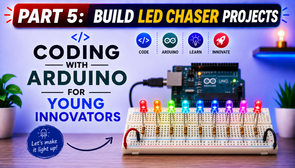
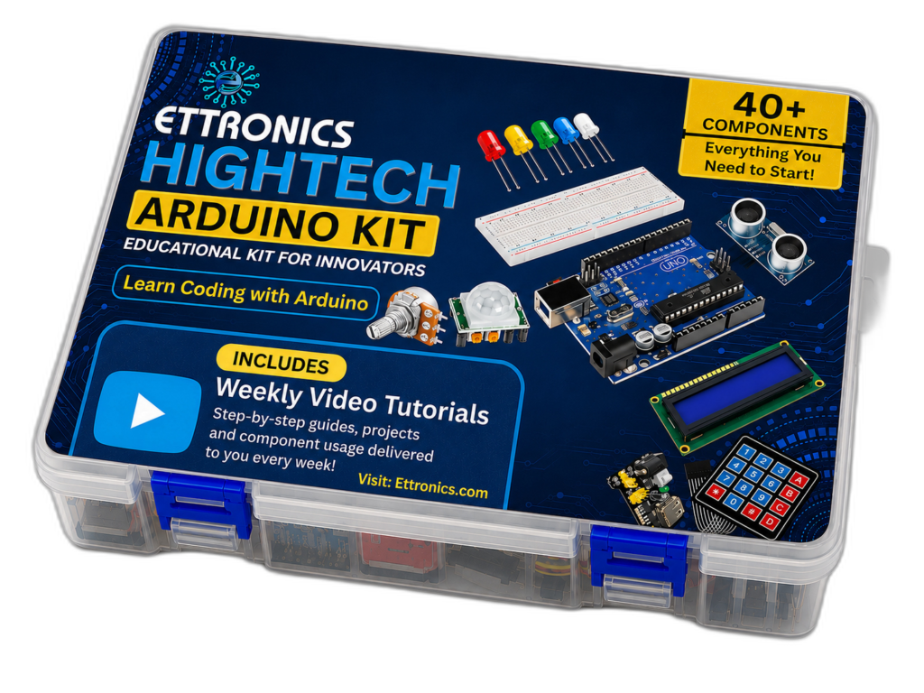
Arduino LED Chaser Circuit Project for Beginners (6 LED Patterns + Bonus Push Button Project) Imagine turning a row of ordinary LEDs into exciting moving light animations with just a few lines of Arduino code. That’s exactly what you’ll build in this tutorial. In this beginner-friendly Arduino project, you’ll learn how to create a fascinating LED Chaser Circuit using an Arduino UNO R3, 10 LEDs, and a breadboard. Instead of simply turning one LED on and off, you’ll control multiple LEDs to create animated lighting effects that move, bounce, and flow across the circuit. By the end of this tutorial, you’ll not only understand how to control multiple LEDs individually but also how to write cleaner Arduino programs using loops, arrays, and functions. We’ll even build a bonus project that uses a push button to switch between six different LED chaser patterns, making the project interactive and much more fun. Whether you’re a child learning Arduino for the first time, a parent teaching STEM at home, a teacher introducing electronics in the classroom, or simply a beginner interested in coding, this project provides an enjoyable way to practice both programming and circuit design. In this guide, you’ll learn: If you’ve already completed our LED Blinking Project, this lesson is the perfect next step because it introduces more advanced programming concepts while still being easy enough for complete beginners to follow. Let’s start by understanding what an LED chaser circuit is and why it’s one of the most popular beginner Arduino projects. What You Will Build By the end of this project, you will have built an exciting Arduino-powered LED chaser capable of displaying six different lighting animations. Each pattern demonstrates a different way of controlling multiple LEDs using code, helping you understand how timing, loops, and digital outputs work together. The bonus feature of this project is a push button that allows you to switch between the different LED patterns without changing or uploading new code. Simply press the button to cycle through the animations and watch your circuit respond instantly. This project is an excellent introduction to creating interactive electronic systems and lays the foundation for more advanced Arduino projects involving displays, motors, sensors, and robotics. Skills You Will Learn After completing this tutorial, you will be able to: What Is an LED Chaser Circuit? An LED chaser circuit is an electronic circuit in which multiple LEDs turn on and off in a programmed sequence, creating the illusion of moving or flowing light. Instead of illuminating all the LEDs at the same time, the lights are activated one after another according to a specific pattern. The movement of the lights is controlled entirely by software running on the Arduino. By changing just a few lines of code, you can create countless lighting effects, from a simple left-to-right chase to more advanced animations that move in opposite directions, bounce back and forth, or light up randomly. An LED chaser is one of the most popular beginner electronics projects because it combines two essential skills: Unlike the basic LED Blink project, where only one LED is controlled, this project introduces multiple digital outputs working together. As a result, you’ll gain a better understanding of how microcontrollers can coordinate several devices simultaneously. How Does an LED Chaser Work? The Arduino UNO controls each LED through one of its digital output pins. When a digital pin is set HIGH, the corresponding LED receives voltage and lights up. When the pin is set LOW, the LED turns off. By rapidly switching different pins on and off in a carefully timed sequence, the Arduino creates the appearance of a moving light. Although only one or a few LEDs may be on at any given moment, the switching happens so quickly that our eyes perceive a smooth animation. The speed of the animation is controlled by the delay() function. Short delays produce fast-moving effects, while longer delays create slower, more noticeable light movements. As you progress through this tutorial, you’ll discover that even simple programming structures, such as for loops, arrays, and functions, can produce surprisingly impressive visual effects. Real-World Applications of LED Chaser Circuits Although this project is designed for learning, the same principles are used in many real-world electronic systems. Understanding how an LED chaser works provides a foundation for designing more advanced control systems in the future. Some common applications include: Many of these systems use the same idea you’re learning here: turning outputs on and off in a carefully timed sequence to create meaningful visual effects. Why This Project Is Great for Beginners The LED Chaser Project builds directly on the skills learned in the LED Blink Project while introducing several important programming concepts without becoming overwhelming. By completing this project, you’ll practice: These are foundational skills you’ll use repeatedly as you move on to more advanced Arduino projects involving LCDs, sensors, motors, robotics, and the Internet of Things (IoT). What You Will Learn in This Tutorial By the end of this guide, you will be able to: These skills will not only help you complete this project but will also prepare you for more advanced Arduino programming challenges in future lessons. Components Required for the Arduino LED Chaser Project Before we start building the circuit, let’s gather all the components you’ll need. One of the best things about this project is that it uses inexpensive, readily available parts, making it perfect for beginners, students, and STEM classrooms. The components used for this project part of the components in out ettronics Coding with Arduino Kit. Unlike the LED Blink Project, which uses just one LED, this tutorial uses 10 LEDs to create exciting lighting animations. Each LED is connected to a separate Arduino digital pin, allowing the microcontroller to control them individually and produce different chasing patterns. The table below lists all the materials required and explains why each one is important. Component Quantity Purpose Arduino UNO R3 1 The microcontroller that controls the LEDs and executes the program. Breadboard 1

Coding with Arduino for Beginners
Coding with Arduino, TUTORIALS

Arduino LED Blink Tutorial for Beginners | Coding with Arduino for Young Innovators

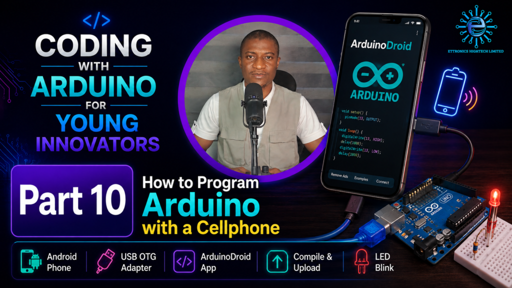
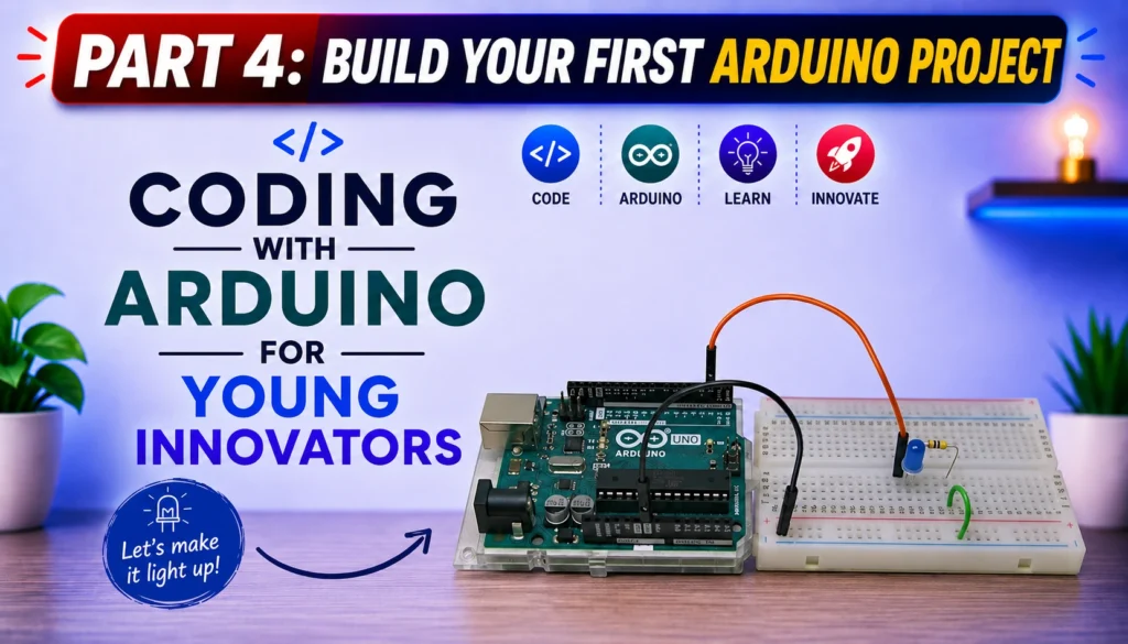
Arduino LED Blink Tutorial for Beginners (Step-by-Step Guide) Learning to program an Arduino is one of the most exciting ways to begin your journey into electronics, robotics, and embedded systems. If you’ve never written a line of code before, don’t worry, this tutorial is designed specifically for beginners, children, parents, teachers, and aspiring innovators who want to learn through practical, hands-on projects. In this lesson, you’ll build one of the most famous beginner projects in electronics: the Arduino LED Blink Project. Although it may seem simple, this project introduces nearly every fundamental concept you’ll use in future Arduino programming, including writing code, uploading programs to a microcontroller, controlling digital outputs, and understanding how a program executes continuously. Whether your goal is to build robots, smart home systems, IoT devices, automation projects, or simply learn programming from scratch, the LED Blink project is the perfect place to start. This tutorial is part of our Coding with Arduino for Young Innovators series, where every lesson builds practical skills through easy-to-understand explanations and exciting projects. Why Every Beginner Starts with the LED Blink Project If you’ve ever searched online for beginner Arduino projects, you’ve probably noticed that almost everyone starts with blinking an LED. That’s not because it’s the easiest project, it’s because it teaches almost every basic programming concept you’ll need later. By completing this project, you’ll learn how to: These skills become the foundation for more advanced projects involving sensors, LCD displays, motors, Bluetooth, Wi-Fi, IoT, and robotics. What You Will Learn By the end of this tutorial, you will understand: If this is your very first Arduino project, you’re in the right place. What Is Arduino? Arduino is an open-source electronics platform that combines both hardware and software to make programming electronic devices simple and accessible. Instead of designing complex electronic circuits from scratch, Arduino provides a programmable microcontroller board that can interact with the outside world. By writing a few lines of code, you can control LEDs, motors, sensors, displays, relays, and many other electronic components. The Arduino platform has become one of the most popular learning tools for: One reason Arduino is so popular is its simplicity. Even someone with no programming experience can build useful projects within a few hours. What Is the Arduino UNO R3? For this lesson, we’re using the Arduino UNO R3, one of the most popular development boards in the world. The Arduino UNO R3 is powered by the ATmega328P microcontroller, which acts as the “brain” of the board. It executes the programs you upload and controls the connected electronic components. Some key features of the Arduino UNO R3 include: These features make the Arduino UNO R3 ideal for learning electronics and programming. As you progress through this course, you’ll use these pins to connect sensors, buzzers, LCDs, ultrasonic modules, Bluetooth devices, Wi-Fi modules, and much more. What Is an LED? An LED (Light Emitting Diode) is a small electronic component that emits light when electrical current flows through it. Unlike ordinary light bulbs, LEDs consume very little power while producing bright light, making them ideal for electronic projects. LEDs come in many colors, including: An LED has two legs: Long Leg (Anode) The longer leg is the positive terminal and should be connected toward the positive voltage through a current-limiting resistor. Short Leg (Cathode) The shorter leg is the negative terminal and is connected to Ground (GND). If you connect the LED backward, it will not light up because LEDs only allow current to flow in one direction. Why Do We Need a Resistor? One of the biggest mistakes beginners make is connecting an LED directly to an Arduino pin. This can allow too much current to flow through the LED, potentially damaging both the LED and the Arduino’s output pin. To prevent this, we use a 220 Ω to 330 Ω resistor in series with the LED. You can check out our resistor calculator software. The resistor limits the current flowing through the LED, ensuring safe operation while maintaining sufficient brightness. Think of the resistor as a traffic controller, it slows the flow of electrical current to a safe level. Components Required To complete this project, you’ll need the following components: Component Quantity Arduino UNO R3 1 Breadboard 1 LED 1 220 Ω or 330 Ω Resistor 1 Jumper Wires 2–3 USB Type A to Type B Cable 1 Computer with Arduino IDE 1 These components are inexpensive and form the basis of countless Arduino projects. Installing the Arduino IDE Before you can program your Arduino UNO R3, you need to install the Arduino Integrated Development Environment (IDE). The Arduino IDE is the software used to write, compile, and upload code to your Arduino board. The Arduino IDE is beginner-friendly and works on Windows, macOS, and Linux. It provides a simple code editor, tools for selecting your board and communication port, and a built-in serial monitor for debugging. Step 1: Download the Arduino IDE Visit the official Arduino website and download the latest version of the Arduino IDE that matches your operating system. Choose the installer for: Once the download is complete, run the installer and follow the on-screen instructions. Step 2: Install the Software After downloading: The installation process usually takes only a few minutes. Connecting the Arduino UNO R3 to Your Computer After installing the Arduino IDE, it’s time to connect your Arduino board. Use a USB Type-A to Type-B cable (often called a printer USB cable). Plug: If everything is connected correctly: Configuring the Arduino IDE Before uploading your program, you must tell the Arduino IDE which board you’re using and which communication port it is connected to. Selecting the Board In the Arduino IDE: This ensures the IDE compiles your code for the correct microcontroller. Selecting the COM Port Next: If you’re unsure which port is correct: Selecting the wrong port will prevent the IDE from uploading your code. Building the LED Blink Circuit Now comes the fun part, building your first electronic circuit. Although the

Scroll to Top